Top of the hip roof. How to make a hipped, equilateral hipped roof for a cottage
In ancient times, our ancestors built their homes in the form of tents. Used for this natural materials: wood, stone, animal skins, etc. The modern tent house is a more fundamental structure. It has several varieties and is endowed with certain technical properties.
Ready-made house project with a hip roof
They can be of two types:
- Full-fledged, built in the form of a tent;
- Incomplete, when they are erected as an ordinary building, the roof structure of which is hipped.
The houses will differ in construction technologies and materials used in the work process.
Characteristics of full-fledged tent houses
Such buildings have. Quite often they can be found on summer cottages. Construction is economical, and the assembly of the structure itself is quite simple.
So, a tent house is based on a frame. The projects are quite varied. You can create them yourself or seek help from a professional architect.
Projects for tent houses are drawn up in a similar way to planning a roof structure of this type.
Only the load-bearing walls of the house, for which slopes will be used, are not taken into account.
 Option for a house project with a hip roof
 Their shape can be with one or two slopes, with four, or multi-slope.
That is, in fact, a tent house is a roof that is immediately installed on a prepared base.
The most interesting are the projects of houses with multi-slope walls. The number of such slopes can be any.
But it’s worth considering that the functionality of such a house may decrease, since it will be quite a large number of limited space due to the construction of additional supporting frame elements.
The most functional and practical are houses with one, two and four slopes. Distributing space in them is much easier.
Note. It is worth considering that the height of such a house can be any. But it is necessary to make it in such a way that the ceilings inside the house reach at least 2.4-2.5 m. In this case, the walls will be inclined.
Although you can make them even and, accordingly, slightly reduce the usable area of the house.
 Hip roof design diagram
 There are several ways to operate a building. Firstly, you can use a tent house only in summer time. In this case, a large amount of money is not spent on its construction. Secondly, you can live in it all year round, which requires high-quality insulation and insulation work. Especially if houses with a hip roof are built from familiar building materials.
How to build a tent house
First, you need to select building designs, which are divided into foundation plans and structure walls. Secondly, you need to initially decide on the choice of building materials. The cost of the future home will depend on them.
So, as soon as there is an exact certainty with all this, you can begin work, which is divided into several stages:
All these stages have their own characteristics.
Selection and construction of the foundation
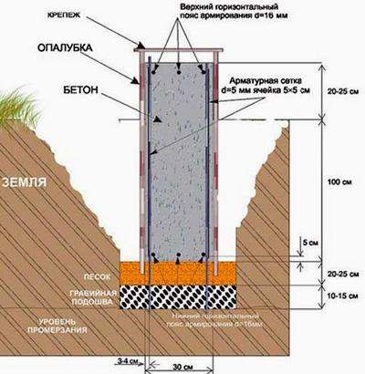
To build a high-quality tent house, you need to choose the right foundation for it. The following foundations are very popular:
Foundation designs are drawn up in advance, after the selection of building materials. For example, if metal is preferred for the construction of the frame, then it is better to make a monolithic or pile foundation for such a house. They are considered the most durable.
The first type is characterized by production using concrete mortar and reinforcement. And the second is made using metal piles, which are also concreted in the ground at a certain depth.

In most cases, strip and tile foundations are constructed under the wooden frame of a tent house, since the material itself does not have much mass.
- Determine the composition of the soil on the site;
- Establish the groundwater level;
- Define specifications terrain.
The last requirement is characterized by studying the terrain: are there any unevenness, slopes and other defects on the site. On such planes, only a pile or pile-tape foundation is preferred.
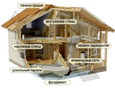
Construction of a frame for a building
As mentioned above, a full-fledged tent house is based on a frame. It is constructed from two materials: metal and wood.
 Detailed project of a two-story house
 Note. You can give preference to special profiles. But this is the case if the structure is light, and its period of operation is limited to the warm season.
First you need to draw up design plans. They will allow you to correctly calculate the amount necessary materials for the construction of the frame.
The elements are as follows:
- Bearing (support);
- Additional (supporting);
- Auxiliary (partitions between small cells).
In its principle, the design resembles the frame of a hip roof. All elements are connected with special fasteners, and a bedding made of roofing felt sheets is first constructed on the foundation.
Important. There should be pins and hooks on the surface of the base that serve to secure the frame to it.
It is to them that they are welded or screwed load-bearing beams frame.
External and internal finishing of the frame
Firstly, the tent house must be properly lined. Secondly, do not forget about insulation and insulation work. When they are carried out, modern sheet materials such as polystyrene foam, polyurethane foam and polystyrene foam are used.
In rare cases, preference is given to mineral wool.
Important. This material is least often used in home insulation tent-type. This is due to the fact that over time it loses its properties and is able to absorb moisture.
Projects for cladding tent houses are quite varied. Today there are a lot of means and materials to make the appearance of a building unique.
Initially, they are mounted on the surface of the frame OSB sheets or thick plywood. Insulating or insulating material is already attached to them.
 Scheme of cladding a frame house with a hip roof
 A low sheathing is created on top of it, on which sheets of plywood or OSB are again mounted, prepared using primers. This will give you the opportunity to choose any Decoration Materials for cladding a building.
The following are very popular now:
- Wood;
- Decorative cladding panels;
- Plaster;
- Plastic lining;
- Natural and artificial stone.
The latter material has a large mass and it is not recommended to install it without surface reinforcement. It is best to use stone to finish the lower part of houses.
The inside of a home may look different. For example, you can leave the walls of the building inclined or build a profile frame that will level them. It is fixed on the slope of the structure and on floor surface. You can already install OSB, plasterboard, and plywood on top.
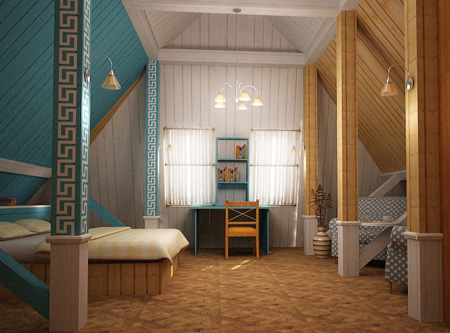 Example of a frame house interior
 The surface of these materials is treated with a primer and finished with any modern materials. You can also pre-insulate and insulate the house using similar products with outside.
The tent house is quite simple design. It must be airtight, since there is no roof in such a structure.
Hip roof is a fairly popular design today. Building your own house on a personal plot or in a village involves installing a roof a certain shape, which you need to choose based on personal preferences.
Hip roofing is considered a classic version of a pitched roof, resistant to wind and snow.
The hip roof design resembles a tent. You should know that you can install such a roof yourself. To do this, you will need to make the correct calculation. It is important to have at least the slightest idea about the design of the rafters of a private house. The roof is fixed in the same way as on other roofs.
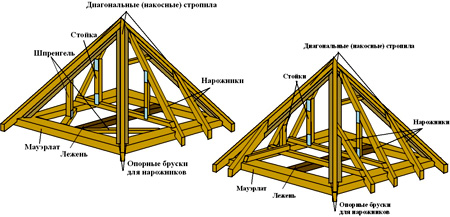
A diagram of the frame structure of a hip roof is shown in Fig. 1.
A hipped roof can have many slopes or be round, it is only important to maintain symmetry. In appearance, the structure resembles a tent. Such products do not have gables, which makes it possible to significantly save on materials during the construction process.
Advantages and disadvantages of a hip roof
If you wish, you can make a hip roof on any building with your own hands. However, the preferred option is when the base of a private house is made in the shape of a square.
The main advantage of a hipped roof of this type is aerodynamics, which can protect the building from constant winds. Air flows will flow down the slopes without causing harm or entering the attic.

Figure 1. Scheme of the frame structure of a hip roof: 1 - corner rafter; 2 - short rafters; 3 - ridge beam; 4 - central intermediate rafters; 5 - intermediate rafters.
Significant disadvantages are the following:
- Complex frame structure.
- Small attic sizes. The area is equal to the area of the ceiling, but the useful volume is small.
A standard hip roof is a pyramid with a rectangular or square base. In the first case, the installation of 4 triangular slopes is provided, and in the second - 2 triangular and 2 trapezoidal. All slopes can rest on the walls of a private house or extend beyond them.
The roof diagram of a private house is simple; its calculation can be done in several ways. The hip roof is constructed using the Pythagorean table. Calculating the area of the slopes and hips is very simple, but calculating the placement of the slanted rafter legs will take a lot of time.
First of all, you will need to assemble it yourself frame structure. After this, the installation of a hipped or gable roof is carried out. You should know that the construction of the rafter system in this case will not be easy.
Return to contents
Points to consider
In order for the roof to be manufactured correctly, the following rules must be followed:
- When constructing the ridge system and rafters, the same type of wood should be used.
- The intermediate slats must have a strong slope, so they minimum size is 150x50 mm.
- Elements of short length are attached to rafter parts, which are placed in the corners. Short parts are not allowed to be attached to the ridge rail.
- The design requires the use of intermediate rafter legs, which are placed in the central part of the product. They are mounted on a ridge rail.
- These elements must be rested against the upper part of the trim and against the ridge rail. To complete the installation yourself, you will need to imagine the frame structure and prepare a drawing.

It is important to consider the following nuances:
- The ridge must be a load-bearing axle.
- Sloping slats will be used as the power components of the rafter system, one part of which should protrude beyond the boundaries of the private house, and the other should be fixed to the ridge.
- The central rafter legs must be fixed at the ends of the ridge and brought out to all the walls.
- Intermediate rafter legs should extend from the ridge.
Elements that need to be prepared in order to build a hip roof with your own hands:
- jigsaw;
- hammer;
- self-tapping screws;
- drill;
- bars and slats;
- roofing material;
- metal staples (you can make them yourself from a 9-10 mm rod).
Return to contents
Sequence of actions for making a hip roof
The roof must be installed before the ceiling is installed. First of all, timber should be laid along the perimeter of the building (on top of the walls) in order to distribute the weight over the entire base. You can use a beam made of wood or metal as a beam. The element is called the Mauerlat. It can be secured with special pins. Next you need to do the following:

- First of all, the axis is marked along the top trim. You need to mark from the end of the building.
- Next you need to calculate ½ the thickness of the ridge strip and mark the installation location initial element rafter systems.
- After this, the measuring bar must be attached to the marked line and the installation location of the intermediate marker must be marked. rafter leg.
- The placement of the remaining elements of the rafters must be calculated by moving the plank along the side wall and marking the location of each rafter leg.
- The steps must be repeated with other angles.
In the process of preparing a hip roof with your own hands, you need to use several types of trusses. These are the slopes of an ordinary truss, which are fastened at the ridge. Additionally, you can use side triangular rafter legs. When installing them, you need to pay attention to the absence of discrepancies in the length and inclination of these parts. They must be clearly verified for all parties. The length of the overhang should be chosen based on the characteristics of the building. The maximum value is 1 m.
To increase the strength of the tent structure, during installation you can use a transverse beam, which strengthens the central rafter system.
The design of the rafter system directly depends on the choice of roof type. The hip roof rearranges itself into a rectangle, the construction of which is considered one of the most complex. The design has four identical slopes, but if desired, their number can be changed, the main thing is to maintain symmetry. In this article we will tell you how rafter system hip roof.
The photo shows a diagram of the structure of the rafters of the tent structure.
The hip roof belongs to the hipped type of structure and has the shape of a tent. The design of the rafter system is presented in the form of an isosceles triangle, connecting at one point, and the base is made in the form of a polygon. The square base of a hip-type roof is considered classic, however, its structure can be made in a different form. A hipped hip roof can be made in the following configuration:
- trapezoidal slopes;
- attic roof;
- bay or yand roof;
- domed slopes and round base;
- presence of six or eight bases.
For information! When installing a classic form, it is recommended to use calculations for the rafter system of a hip roof, taking into account current building codes and regulations.
Advantages and disadvantages

The photo shows a house with a hip roof. Despite the complexity of the rafter system of a tent structure, its popularity in the design of private houses is quite high. Experts note the following advantages of the tent structure:
- High aerodynamic characteristics, allowing you to reliably protect a hip-type roof from strong and squally gusts of wind, without tearing it off roofing material and collapse attic space;
- The presence of steep slopes eliminates the process of cleaning the roof from snow and debris;
- Hip roof allows for expansion usable area at home and equip the attic;
- Gives an original appearance to any structure;
- High structural strength, reliable protection from freezing and precipitation.
The disadvantages include the following:
- A large amount of consumables;
- The absence of gables presupposes the installation skylights, which are fixed directly into the slope.
Construction of a tent structure

A hipped hipped roof and rafter system can be constructed in two ways: hanging or sloping. A set of inclined rafters is considered the most economical and simplest to install. The main structural elements of a hip roof consist of:
- Ridge knot - an element where all the rafter legs are connected, forming its apex point;
- The presence of a triangular-shaped slope, rafters provide support and form the surface of the structure. The angle of inclination should be 20-50 degrees, regardless of the number of roof corners;
- Overhangs - this element performs protective function buildings from precipitation and wind gusts. The fillies and rafter legs are responsible for the high-quality formation of overhangs.
For information! Overhangs can reliably protect a building provided that the element length is permissible, so when making calculations, take into account the overhang length of at least 50 cm.
- Roof covering - construction material, covering the rafter system of the entire structure. The main task of roofing material is to protect the entire surface from the penetration of snow, rain and cold. Most often, metal tiles, slate, roofing felt, and ondulin are used as materials.
- Rafter system - important element tent structure, performs a support function, is able to reflect the load and prevents the destruction of the foundation and load-bearing elements of the structure;
- Drainage system- is responsible for the unhindered release of moisture into storm drainage. The complex includes vertical pipes, funnels and gutters.
Features of the rafter system

Tent roofing structures can be made using a layered or hanging system. Hanging rafters are installed when there are no internal walls in the house, and the rafter system rests directly on bearing structures Houses. The photo shows the technical characteristics of the hanging rafter system. The system of layered rafters involves fixation to the middle load-bearing wall or to support pillars, which are firmly fixed with reinforced concrete.
For information! For hipped roofs With an inclination angle of 40 degrees and above, it is recommended to perform layered rafters.
An important point is correct selection supports for the rafter system. For example, for frame structure use the top harness, brick house the function of support is played by the mauerlat, and in log houses the upper crowns are used.
Calculation of the hip rafter system

The following measurements will help you avoid mistakes and complete all calculations:
- eaves overhang length;
- basic parameters of slopes (angle of inclination, length, width);
- type of base shape,
- width and length of the roof base.
When all the calculations have been completed, a drawing of the rafter complex should be made. As a rule, for this you can use a special online service, with which you can make correct calculations roofing material.
If you turn to specialists for help, design future design begins with making a drawing, namely drawing the outlines of the structure. When drawing a roof, the height of the structure does not depend on the height of the walls, however, this parameter should be taken into account when calculating snow and wind loads.
For information! At a small angle of inclination, there is a risk of precipitation stagnation on the entire roof plane. Experts recommend using an inclination angle of 30-60 degrees.
You can learn more about how to independently calculate the rafter system of a hip roof from the video.
The calculation of the rafter system is carried out using the Pythagorean theorem. If the base of the structure is square, the slopes will be like an isosceles triangle with the same angle of inclination and their dimensions. To simplify the task, it is recommended to calculate the rafters on one element and transfer the obtained data to the remaining fragments of the complex.
The tent design assumes too high consumption building and roofing materials, because When carrying out the work it will be necessary to make a large number of cuts. However, this quality and reliable roof will be able to protect the house from various influences of the external environment, and its original appearance will attract the attention of others.
A hip roof can be one- or two-level, have four or more slopes. To correctly select the sections of its elements, it is necessary to perform a sketch and correct calculation, which comes down to several formulas. In the article we will talk about the design of a hip roof and the method for calculating its rafter system.
A hip roof is one of the most common options when building a house or gazebo that has a circular, square or rectangular plan with a slight difference in the lengths of the sides. This design is a good solution for relatively small houses. large area or two-story cottages with a small base. The roof got its name because of the pyramidal shape of the traditional eastern tent, formed by one peak and triangular slopes.
Hip roof options
The name “hipped roof” combines several roofing options that have structural differences.

Single-level hipped roof geometrically it is a tetrahedral pyramid. A two-level roof is a more complex structure: top part- a pyramid, the middle one is a cube or parallelogram, the bottom one is a truncated pyramid. It was as if the top of the roof had been cut off from the base and lifted up. The middle part is sometimes made in the form of a glass lantern or finished in the color of the walls.

A hip roof can have not only four slopes, but also six or eight slopes. This shape is more reminiscent of a cone than a pyramid, and is most common when building gazebos with a round base. The most difficult thing in implementing such a design is connecting the rafters in the center.


The rafter systems differ not so much aesthetically as structurally:
- hanging;
- layered.
A hanging rafter system rests exclusively on the walls of the house, while a suspended rafter system has a support located in the center of the building and rests on a load-bearing wall or on a pillar specially erected inside the house.
 a - design of hanging rafters; b - design of layered rafters; 1 - rafter; 2 - crossbar; 3 - tightening; 4 - stand; 5 - strut; 6 - run; 7 - lying down
The choice of design depends on the size of the span (8 m - a hanging system is suitable, 12 m - a layered system is required) and maximum length timber for construction (when connecting a rafter leg in length, installation of a vertical support is required).
In practice, a layered system is often used as it is more reliable and maintainable. If there is no suitable bearing wall or a pillar for support, the base can be created from timber by bandaging at the level of the mauerlat.
Basic diagrams and elements of the rafter system
As we wrote, a hipped roof is geometrically a pyramid, so all calculations are carried out based on the rules that apply to the pyramids and triangles that make it up.

Essential elements
In order not to be confused in the future with terms, we will name the main elements of the rafter system of a hipped roof, schematically shown in the figure below, and tie them to the geometric image of a hipped roof in the form of a pyramid.
 Hanging rafter construction
- Mauerlat. The foundation and support of a roof, especially in a structure with hanging rafters. It is located along the perimeter of the building (ABCD), rests on the walls or is attached to their outside. To construct the Mauerlat, large cross-section timber is used.
- Sloping rafters. Roof angles that converge at a central point and form a pyramid. On the pyramid diagram (without taking into account overhangs): AK = DK = CK = BK = Lн. The longest rafter legs in the structure.
- Ridge knot (K). The most difficult knot in a structure for a carpenter. If the base of the house is not square, and the ridge forms an edge, the hip roof is transformed into its “sister” - a ridge roof. In a structure with layered rafters, section KF (H) is the central support.
- Central rafters. They converge at the ridge unit with slanted rafters. They are the height of each slope, which is an isosceles triangle. On the diagram of the pyramid (without taking into account the overhangs) there is a segment KE, length Lt.
- Narozhniki. These are shortened rafters running parallel to the central one in both directions.
Now consider structures with layered rafters.
 Transomless design with layered rafters
Along with the already designated elements: slanted (1) and central (2) rafters, as well as the ridge (3), new elements appear. The central support (stand) or headstock (4), which rests on the ties (5) connecting the mauerlat diagonally. This is an option for making a rack that rests not on the masonry, but on an element of the rafter system.

In the absence of central rafters and to strengthen the ridge assembly with the headstock (2), it is supplemented by crossbars (3), connecting oppositely placed sloping rafters (1) in pairs (see figure above).
Reinforcement elements
For greater strength and rigidity of the structure, especially in a climate prone to strong winds, or with a large building area, and therefore a large length of rafter legs, the main structural elements are supplemented with reinforcement elements.
 Option to strengthen the truss structure
Along the axis of the building, a additional beam- lying down (2). The basis of the structure, as before, is made up of central (4), shortened (springs) (5) and slanted (3) rafters. The slanted rafters are reinforced by cranial bars (6), fixed at the bottom. This is a reinforcement for both the mowed legs and the riggers leaning on them. The ties (7) fasten the oppositely located rafters and serve as a base for installing the racks (8). They are fixed on top of the Mauerlat and on top of the bench and rest on them.
For particularly long rafter legs, struts are used - supports that are not located vertically, but at an angle of 45-60°. In practice, struts are installed when the length of the wall is more than 9 m (for a gable or four-pitch wall).
The system of strengthening the main elements also helps to save lumber. The cross-section of the main elements in such a design can be taken to be reduced. Another way to save is the formation of overhangs by adding rafters ending on the mauerlat with fillets - bars or boards of a smaller cross-section.

Calculation of the rafter system of a hip roof
The calculation is based on the following initial data:
- length of the house;
- width of the house
- ridge height.
Let's consider the procedure and formulas for calculations using a conditional example, using the geometric image of a hip roof (see above):
- house length: AB = DC = 9 m;
- house width: AD = BC = 8 m;
- height of the ridge located in the geometric center of the roof: KF = 2 m.
Calculation of the lengths of rafter elements
1. Length of beams Mauerlat.
- AB + DC + AD + BC = 9 + 8 + 9 + 8 = 34 m
2. Central rafters(excluding overhangs). Are the hypotenuse right triangle, in which one leg is the height of the ridge, and the second is half the width (8/2 = 4 m) or length (9/2 = 4.5 m) of the house.
Let's remember the Pythagorean theorem:


3. Sloping rafters(excluding overhangs). They are the hypotenuse of a right triangle, in which one leg is half the width or length of the house, and the second is the corresponding central rafter. For a roof with a ridge in the geometric center of the roof, the lengths of the slanted rafters are the same.

4. Narozhniki. The shortened rafters are located parallel to the central one, with a pitch depending on the length of the rafters. Let's consider a table compiled taking into account weather loads for the Moscow region.
Table 1. Data correspond to atmospheric loads in the Moscow region
| Rafter spacing, cm | Rafter length, m | ||||||
| 3,0 | 3,5 | 4,0 | 4,5 | 5,0 | 5,5 | 6,0 | |
| 215 | 100x150 | 100x175 | 100x200 | 100x200 | 100x250 | 100x250 | — |
| 175 | 75x150 | 75x200 | 75x200 | 100x200 | 100x200 | 100x200 | 100x250 |
| 140 | 75x125 | 75x125 | 75x200 | 75x200 | 75x200 | 100x200 | 100x200 |
| 110 | 75x150 | 75x150 | 75x175 | 75x175 | 75x200 | 75x200 | 100x200 |
| 90 | 50x150 | 50x175 | 50x200 | 75x175 | 75x175 | 75x200 | 75x200 |
| 60 | 40x150 | 40x175 | 50x150 | 50x150 | 50x175 | 50x200 | 50x200 |
Our central rafters are 4.472 m long and 4.924 m long. The rafters will be shorter, so you can look at the column - 3.5 m.
To calculate the lengths of narozhniks, let’s remember school and use the properties of similar triangles.

If in the figure AB is the central rafter, then MN is the frame, AC is half the length of the wall (4.0 and 4.5 m, respectively), AM is the step depending on the number of frames. MC for each narozhnik is calculated separately.
- MN = (AB · MC) / AC
We will calculate the options for choosing the most economical arrangement of shortened rafters, the results of which will be summarized in a table.
Table 2. Calculation of lumber for frames
| Pride step, cm | Beam cross-section, mm | Long side bars: AC = 4.5 m, AB = 4.472 m | Short side spigots: AC = 4.0 m, AB = 4.9242 m | ||||||
| quantity per half slope | AM, m | length in half slope, m | quantity per half slope | AM, m | length in half slope, m | volume of lumber for two slopes, m3 | |||
| 215 | 100x175 | 1 | 2,25 | 2,356 | 0,165 | 1 | 2,0 | 2,461 | 0,172 |
| 175 | 75x200 | 2 | 1,5 | 2,981 + 1,491 | 0,268 | 1 | 2,0 | 2,461 | 0,148 |
| 140 | 75x175 | 2 | 1,5 | 2,981 + 1,491 | 0,235 | 2 | 1,333 | 3,282 + 1,641 | 0,258 |
| 110 | 75x150 | 3 | 1,125 | 3,354 + 2,236 + 1,118 | 0,302 | 3 | 1,0 | 3,693 + 2,462 + 1,231 | 0,332 |
| 90 | 50x175 | 4 | 0,9 | 3,578 + 2,683 + 1,789 + 0,894 | 0,313 | 3 | 1,0 | 3,693 + 2,462 + 1,231 | 0,259 |
| 60 | 40x175 | 6 | 0,643 | 3,834 + 3,195 + 2,556 + 1,917 + 1,278 + 0,639 | 0,376 | 6 | 0,571 | 4,218 + 3,515 + 2,812 + 2,109 + 1,406 + 0,703 | 0,413 |
Obviously, for our example, options with long steps are less expensive. However, you should also take into account the requirements for fastening the roofing material and the costs of the sheathing. From this point of view, the answer will not be so obvious.
Calculation of roof area taking into account overhangs
Since the previous calculation was made without taking into account the eaves overhang, which in our example is performed using fillies, we will consider this part of the roof again as a simple geometric figure.

Let us take the length of the overhang (DC) to be 0.5 m. To determine the area of the slope, we again use knowledge about the properties of similar triangles:
- EF / BC = AG / AD
BC - 8 and 9 m for short and long walls respectively.
AD - 4.924 and 4.472 m for short and long walls, respectively.
AG - 4.924 + 0.5 = 5.424 m and 4.472 + 0.5 = 4.972 m for the short and long walls, respectively.
- EF = (AG ∙ BC) / AD
- EF = (5.424 ∙ 8) / 4.924 = 8.812 m - for the short side
- EF = (4.972 ∙ 9) / 4.472 = 10.006 m - for the long side
The area of the slope is calculated using the formula:
- S = (EF ∙ AG) / 2
- S = (8.812 ∙ 5.424) / 2 = 23.9 m 2 - for the short side
- S = (10.006 ∙ 4.972) / 2 = 24.88 m 2 - for the long side
Total area of roofing material:
- 2 (23.9 + 24.88) = 97.56 m2.
Advice! When calculating the material, take into account the cutting, especially if it is sheet material, such as slate or corrugated board.

Attention! The article discusses the calculation of only the main elements of the rafter system, which can help in drawing up a preliminary construction budget.
Some owners of country housing seem too banal and uninteresting, and they begin to search for more original options. These include a tent structure that looks extremely interesting in appearance, as if it came straight out of an illustration in a history textbook or a book of children's fairy tales.
Despite its apparent simplicity, the rafter system of a hip roof is one of the most complex to construct. Taking on the construction of such a structure on your own, without having experience in such work, will be very risky. However, for those who want to opt for just such a design, it will be useful to obtain information on the structure of the system, its main components, and how to carry out basic calculations. It is in this context that this publication will be constructed. We hope that it will help you understand the nuances of the hip rafter system, really appreciate its complexity and the possibility of self-installation.
What is a tent rafter system?
In fact, a hipped roof geometrically represents a “classical” pyramid, that is, a figure with a polygon at the base and faces that are isosceles triangles converging at a single vertex.
In private construction, a pyramid with a base in the form of a quadrangle is most often used, although for extensions (turrets, bay windows, etc.) or light garden buildings (gazebos) it is practiced to build more complex structures, which can have a regular hexa- or octagon (sometimes even larger).

In this publication, the emphasis will be placed on the hipped hipped roof. Variations are possible here too. A “classic” design is considered to be a pyramidal structure resting on a square base, with the apex located on a perpendicular passing through the point of intersection of the diagonals of the base. In this case, all four slopes will be absolutely congruent triangles located at the same angle of inclination.

The diagram shows a pyramid with a square at the base - this is what we will consider in the future. You will have to return to this drawing more than once throughout the presentation.
It is quite possible to use a tent scheme on a rectangular building whose length exceeds its width. However, in practice this is used infrequently - due to the unnecessary complication of both calculations and installation. With this option, the slopes resting on a shorter wall become longer and have a smaller angle of inclination to the horizon, that is, external loads for them already have to be calculated individually. It is much more suitable for rectangular bases - it is in many ways similar to a tent base, but is better adapted to such conditions.

The hip roof shape provides many significant advantages:

- A house with such a roof stands out very advantageously against the background of standard ones. gable roofs, possessing a peculiar attractiveness.
- In terms of its aerodynamic qualities, that is, its ability to withstand wind loads, especially during squalls or even hurricane gusts, it probably has no equal among pitched roofs. Moreover, the lifting component of the wind load is minimized - the force trying to tear the roof upward.
- The unique pyramidal shape promotes uniform distribution all external and internal loads on the roof system and the building as a whole.
- At proper insulation roof slopes, such a roof - optimal solution from an energy saving point of view.
- At optimal choice the steepness of the roof slopes will not pose any special problems.

The disadvantage, in addition to the certain complexity of the design, is that four identical slopes seriously “eat up” the volume of the attic space, which complicates the organization of “habitable” area in it. To create residential attic, you have to sharply increase the slope of the roof and resort to “inserting” additional windows and superstructures. It is clear that taking on the calculation and construction of such complex design– it’s simply pointless, since it requires highly professional architectural design and installation.
The main elements of a hip rafter system
Let's consider the basic structure of the rafter system of a hip roof. To do this, first let’s take a completely abstract house, the walls of which form a square, and try to fit such a roof to it.

In the context of this article, we are not particularly interested in the roof and walls. Let’s hide them from sight in order to be left “face to face” with, in fact, the very design of the rafter system. Well, then let's look at it in detail.

The walls are hidden from view, but the mauerlat is left (item 1). This is a powerful beam, which is secured with a belt along the upper end of the walls - it is on it that all the rafters will rest. Unlike, for example, a gable roof, in our case it must be a closed frame, rigidly connected - the strength and stability of the entire rafter structure directly depends on this.
From the corners of the mauerlat upward to the center, to the ridge unit (pos. 3), the ribs of the pyramid converge - their role is played by slanted rafters (pos. 2). These are the longest and most loaded of all other rafter legs, and usually the most “powerful” lumber is used for their manufacture - this will be discussed below. In the pyramid drawing they correspond to the segments [KA], [KV], [KS] and [KD]. The length of the layered rafters in the same diagram is designated Lн.
From the center of each side, central rafters run to the same ridge assembly (item 4). They determine the height of the isosceles triangle of each slope. In the drawing, this is, for example, the segment [KE] (rafter length - Lt). In geometry, there is a separate name for this element of the pyramid - apothem.
Finally, from each slanted rafter leg, shortened rafters or flanges (pos. 5), installed at a certain pitch, extend in both directions to the mauerlat. Their number will depend on the overall dimensions of the entire system.
By the way, often, in order not to “overload” the ridge assembly with connections, they refuse to install central rafters and install only the ridges, placing them symmetrically to the apothem.
This diagram shows an option in which all rafters, without exception, from the rafters to the shortest rafter, are made with a protrusion beyond the Mauerlat - to create the necessary eaves overhang. But in the future, all calculations will be carried out for the “net” length - from the ridge bridle to the mauerlat, and the amount of elongation will be calculated separately, depending on the planned width of the overhang and the angle of steepness of the slope.
rafter mount

Very often this is what they do - a powerful rafter beam ends on the mauerlat, and the cornice light is ensured by increasing the length due to special parts - fillies made of thinner boards. This allows you to achieve considerable savings on lumber.
The diagram showed one of the most simple circuits, when the slanted rafters are made according to a hanging pattern and are completely balanced. Let's be honest - this is very rare in reality. In practice, it is necessary to resort to installing additional reinforcing elements that ensure the strength and stability of the rafter system structure.
Firstly, the rafters can be installed using a layered system, that is, supported by a central post. The stand can rest on a solid internal wall (if there is such a possibility), or on a bench laid in the center - a powerful beam resting on opposite external walls building.

1 – slanted rafters;
2 – central post (headstock);
3 – puffs (crossbars).
By the way, when constructing light buildings, for example, gazebos, sometimes the central post is located along the entire height, from the foundation (floor) to the ridge unit, and serves as a kind of “interior” item.
Another option is that the base for the rack is horizontal tie rods (crossbars) connecting opposite rafters. These puffs can be located at the bottom, closer to, or approximately in the middle of the height of the “pyramid”. Sometimes such crossbars serve as the basis for lining the roof of an attic space.

The figure shows an example when slanted rafter legs (pos. 1) are connected diagonally with ties (pos. 5). At the intersection of the tie rods, a central support is mounted (item 4). All rafters, including the central ones (pos. 2) are connected to a support (headstock), thereby forming a ridge unit (pos. 3).
Often the center post is not used at all. On small roofs, structural rigidity is ensured simply by reliable fastening of the central and slanted rafters on the mauerlat and in the ridge assembly. In the ridge, the rafters are adjusted to each other by cuts at a certain angle, and then this connection is reinforced with metal plates. Another option is to use a central insert element to which the rafter legs are attached.
metal tiles

But with large lengths of rafters, sometimes - even if the rafters are too long, they still require reinforcement. For this purpose they can be used additional elements systems.

This illustration shows one of the options. In the center of the square formed by the mauerlat (item 1) there is a frame (item 2) embedded. As in the usual scheme, the sloping (item 3) and central (item 4) rafters and spigots (item 5) are installed.
At the bottom of the slanted rafter legs, cranial bars (item 6) are reinforced - they serve for more reliable support for the installed spigots.
Both the central legs and the spouts are connected to the opposite, symmetrically located parts with the help of ties (item 7). The ties of the lower row, to avoid deflection in the center, rest on the bench, and at the same time serve as a support for the upper row, perpendicular to them.
From the ties to each central rafter leg and to the spouts there are vertical posts (item 8).
Instead of vertical posts (or together with them), struts can be used - supporting elements located at an angle to the horizontal. This can be convenient when the main load needs to be transferred to one central point (for example, a beam or a major lintel inside a building), and not distributed over the tightening. The struts are usually placed at an angle of 45÷60°. They find application if the length of the rafter legs exceeds 4.5 meters. Such additional support points make it possible to reduce the cross-section of lumber used for the manufacture of rafters, that is, to both lighten and reduce the cost of the entire system structure.

The illustration shows two options. On the left is a combined one, in which both the stand (item 2) and the struts (item 3) are attached to the bed (item 1). In the right picture, we did without a stand, and only two struts rest against the bed, going up to the symmetrical rafter legs.
The diagram also shows connecting parts - metal dowels (item 4) and steel brackets (item 5).
As already mentioned, the longest and most concentrated loads are the slanted (diagonal) rafter legs. Not only are they usually thicker than others, but they often have to be additionally supported to prevent sagging or torsion. For this, the same struts extending from the central support, or a special system unit called a truss support, can be used.

This unit is a truss beam (pos. 9) that cuts into the mauerlat at the corner, and from which a stand (pos. 10) extends vertically upward, supporting the slanted rafter leg. Sometimes, on large roofs, it is necessary to install a simple truss, and a truss truss, that is, to strengthen vertical stand struts.

There are other options for installing and strengthening the rafter system of a hip roof - many craftsmen use their own techniques, developed and proven over the years. But the basic principle still remains the same as shown above.
Now it is necessary to consider a block of questions related to linear dimensions main parts of the structure, with the cross-section of lumber necessary for their manufacture, with other geometric parameters the created system. In a word, you need to dive into the calculations.
Carrying out basic calculations of the rafter system of a hip roof
Carrying out the proposed calculations will help owners decide in advance on the main characteristics future roof And required quantity materials. Calculations must be carried out in a certain sequence, since most of the parameters are closely interrelated, and, one might say, follow from one another.
The height of the “pyramid”, the slope angle of the slopes and the planned roofing of the hip roof
This group of parameters is highlighted in first place. The listed characteristics are closely related to each other and will be decisive for the rest of the calculations.
Why is it necessary to know the steepness of the slopes in advance? Yes, if only because every owner sees in advance the roof of his future home, “dressed” in one or another roofing covering that he prefers. And when choosing coatings, whether you like it or not, you have to comply with certain requirements - each material has its own maximum permissible limits for the minimum slope.
The fact that the slope depends on the height of the top of the “tent” (and vice versa) probably does not need to be explained - as one parameter increases, so does the second. But the dependence here is not linear, but tangential. Let us turn to the diagram of the “pyramid”.
The height of the ridge unit is indicated N- this is a segment . This vertex itself in horizontal projection lies exactly in the middle of any of the sides of the square forming the base. It turns out to be a right triangle KFE, leg which is known is half the width (length) of the building [AV]. Roof slope angle – α . It is easy to determine the height:
H = 0.5 × [AB] ×tgα
This calculation will be easier to do using the built-in calculator: