Technical inspection of engineering systems. Commissioning work in engineering systems Assessment of the condition of building engineering systems
For directors and other high-ranking representatives of the population of the third planet from the sun
Upon completion, the customer will be issued a certificate and conclusion. As well as confirmation of completed work.
Survey cost calculator utility networks
Select building typeRetail buildings Retail MFC Administrative Industrial Warehouse MFC Residential buildings M2: | Survey Design cost calculation Price design work by main sections from 10,999 m2, Vstr=31,892 m3 |
|
| Settlement and explanatory note | 0 | 0 |
| Analysis of as-built documentation, preparation of a list of defects, photographic recording of the subject of examination | 0 | 0 |
| Power supply system, photographic recording | 0 | 0 |
| Cold water supply system, photo recording | 0 | 0 |
| DHW water supply system, photographic recording | 0 | 0 |
| Drainage system, photographic recording | 0 | 0 |
| Heating ventilation and air conditioning, heating network, photographic recording | 0 | 0 |
| Communication networks, photographic recording | 0 | 0 |
| Gas supply, photographic recording | 0 | 0 |
| Measuring the strength of concrete using the ultrasonic method | 0 | 0 |
| Performs opening of structures, sampling of concrete, determination of composition and reinforcement | 0 | 0 |
| Development of building plans in PDF format based on BTI | 0 | 0 |
| Development of plans for the placement of elements of the internal engineering systems of the building (risers VK, OV, placement of ASU, placement of utility inputs) | 0 | 0 |
| Determination of geological conditions of the construction site (properties of foundation soils) | 0 | 0 |
- Sample for design and survey work - KP, TZ, ESTIMATED technical inspection of engineering systems up to 1500 m2
- Sample for design and survey work - KP, TZ, ESTIMATED technical inspection of structures up to 1500 m2
Utility network survey treatment facilities
Inspection of wastewater treatment plants- begins with compilation terms of reference. The chief engineer or CEO, appointing specialists responsible for specific work. At the end it will be compiled detailed plan, including research results, a list of equipment with recommendations for use and, of course, modernization details.
Water supply system inspection
Water supply system inspection- a set of measures aimed at identifying the actual and obsolescence of the water supply engineering system. Includes a detailed visual inspection by specialists, control using specialized equipment and calculation work. Upon completion, a research report is drawn up detailing the results, recommendations, best practices modernization and maintenance.
Survey electrical networks
Electrical networks survey- usually initiated by the company upon the fact of excessive electricity consumption or the occurrence of an emergency. Networks, electrical installations, and input devices are directly inspected. Based on the issued conclusion, actions are taken to improve, repair, and dismantle systems.
Inspection of engineering networks of ventilation ducts
Inspection of ventilation ducts- this includes checking design documentation and working calculations to assess the feasibility of the installation. Monitoring of the system, air channels and components. Finally, if necessary, recommendations are made for effective use, repair or modernization.
Ventilation system inspection
Ventilation system inspection– comes down to measuring parameters (air flow speed, transparency, amount of suspended particles, humidity) and comparing the obtained data with the calculated data for a specific system. In case of a significant discrepancy, the system is examined for improper operation of units and components.
Ventilation inspection report
 Ventilation inspection report– includes data shown by calculations when designing the system and practical parameters of the operating system. If there is a significant discrepancy between the parameters, measures are indicated to align them.
Exhaust ventilation in production
Exhaust ventilation in production– is extremely necessary for pumping the required amount of clean oxygen-saturated air into the room, removing it outside working area harmful to health human production products. Most best option of all possible systems ventilation in most types of production.
Validity engineering surveys – defined by law as 2-3 years. Results with a period of more than 3 years are included in the history of engineering surveys and are necessary for the conclusion of a repeated reconnaissance study.
Obtaining GPZU, SPOZU in Moscow
 Obtaining GPZU, SPOZU in Moscow– perhaps in the Committee on Urban Planning and Architecture in the city of Moscow, or in the Moscow Committee for Architecture.
First of all, you will need to collect a package of confirmed papers. Term of provision of services from the moment of submission of documents to issue: 30 days.
What is GPZU, SPOZU
What is GPZU, SPOZU– a set of documents prepared accordingly by the responsible person, Planning Organization Scheme land plot or as an abbreviation. Describes in detail the special purpose of a specific territory, characteristics and possibilities for construction.
Samostroy
 Samostroy- a structure erected without proper permitting sanctions and approvals. In places not intended for this.
How to legalize unauthorized construction
How to legalize unauthorized construction– you should start by calling a commission from the local authorities of the municipality. Which will issue the necessary confirmations. The decree legitimizing the construction will be obtained directly from the arbitration court.
Legalization of unauthorized construction
Legalization of unauthorized construction- we apply the latest research and achievements both technically and legally, so that you have the opportunity to solve the problem with minimal effort.
Temporary structure, definition
Temporary structure, definition– structures and buildings are recognized that can be moved without causing disproportionate damage. An integral structure, not connected to the ground and utilities, without a rigid foundation, which is not possible to free without destroying the structure.
List of documents for putting the facility into operation
List of documents for putting the facility into operation– this includes: an application from the developer and investor for the issuance of documents for putting the facility into operation, confirmation of acceptance, a document approving the parameters of the constructed facility in accordance with the current regulations. Papers confirming the compliance of the erected building with the technically approved project.
The procedure for registering land ownership
The procedure for registering land ownership– statements describing the purpose of acquiring rights to the site, a supporting document indicating perpetual use or lifelong ownership and justifying reason. An extract from the household register, an act on the receipt of land, issued by the authority local government. One document confirming the owner of the land. Confirmation of payment of state duty and passport of a citizen of the Russian Federation.
Composition of the redevelopment project
 Composition of the redevelopment project– includes: diagram of partitions, reinforcement of openings. Water supply, sewerage and heating systems.
Plan before work begins. Measures to ensure industrial and fire safety. Confirmation of the project manager.
Cost of the redevelopment project
Cost of the redevelopment project– includes the cost of drawing up a design, sketch and working design.
Author's supervision.
A significant part is the preparation of the necessary documents.
Premises redevelopment project– pursues the goal of ensuring complete structural safety of engineering systems, performance characteristics and building structures. Project design standards are regulated in accordance with GOST 21.101-97 and GOST 21.501-93.
Development of a redevelopment project– begins with the provision of documents from the Bureau of Technical Inventory and a sketch of the redevelopment.
Mezzanine
 Mezzanine- in global practice, an additional room built into the main mass of a building, in Russian architecture - a shelf in the upper part of the room used for storing homemade scrubs.
Sample of an object inspection report
 Sample of an object inspection report- will be filled out by members of the commission that examined the property and made a conclusion. Recording data in the survey report.
Property survey report– a document confirming the readiness of the property for operation. Compiled in relation to newly erected and renovated buildings. Compiled by an authorized commission of administrative authorities. Has the task of improving the overall picture of construction.
Sample certificate of inspection of buildings and structures- a document confirming the inspection of the structure by a group of persons. To carry out the next inspection of the building, only competent persons must be involved, who are obliged to evaluate all identified deficiencies in the building.
Sample building inspection report– cannot be used as a supporting document. Useful to familiarize yourself with the formal rules for filling out reports.
Inspection report building structures
– confirms monitoring and inspection of the condition of building structures and structures. If a defect is identified that cannot be eliminated without dismantling the structures, a separate defect elimination report is drawn up.
Control of building structures
 Control of building structures- carried out upon the construction of a building or structure. In the future, scheduled or unscheduled, it takes place in the presence of a competent commission with registration of the results. And entering data into current documentation for further analysis.
 Expert opinion sample document– used for the initial conclusion. Can be used as secondary confirmation, not suitable as a final expert opinion.
Examination of buildings and structures
 Examination of buildings and structures- aims to determine the residual life and technical condition of buildings and structures. Assessment of the extent to which the constructed structure meets the requirements and the extent to which it complies with industrial safety requirements.
Technical inspection report- carried out to confirm the technical inspection of the building. In order to safely operate a building, a commission of authorized members is required to confirm that the building is ready for use.
Building inspection report, sample– can be downloaded on the website of our organization. Used as a draft version of a document submitted to the competent authorities for greater accuracy and reduction of errors.
Certificate of inspection of buildings and structures- records the state of the object at the present specific moment. It lists the defects in detail. All changes are recorded in writing, after which the document is certified by the customer and interested third-party organizations. Does not reflect the overall technical condition.
Construction site inspection report– compiled at the time of a scheduled or unscheduled inspection of a construction site to identify technical details and compliance of technological operations with technical specifications.
Defecation certificate form– is necessary only in cases where a significant defect in the design of a building or structure is found. The form can be downloaded from the website of the local Rostekhnadzor authority.
Defect report– a document certifying that the building and structure cannot be used for its intended purpose. It has severe defects and needs serious repairs. Compiled by an authorized commission of specialists.
Opening in a load-bearing wall cost - the price consists of the complexity of the technical implementation. The material of the wall, brick, monolithic concrete or a panel house. Based on the material, the tool is chosen. Depending on the chosen tool and the classification of specialists, the final figure is added up.
Opening strengthening project
 Opening strengthening project– is being developed design organizations– members of the SRO or authors of the building project. According to housing legislation, openings in load-bearing walls significantly affect safety. Therefore, they must be properly registered with the Moscow Housing Inspectorate.
Gain metal beams
 Strengthening metal beams- can be local or general. Local reinforcement due to welding of additional stiffeners. General - creation of the lower belt of the trusses, removal of the support stress.
Concrete examination
 Concrete examination- reconciliation of the actual quality of the product with the characteristics shown in the design documentation.
The highest quality strength measurements are carried out using concrete cores removed from the finished structure.
Determination of concrete strength- it is possible to determine by destructive testing, indirect non-destructive and direct non-destructive. Ultrasonic testing. Regardless of the method or equipment, the measurement error is never less than 30%.
Concrete testing laboratory– concrete is a complex composition, and therefore an analysis of each component is necessary for assessment. Laboratory selects required composition concrete depending on the technical specifications, as well as the composition of gravel, cement, sand. Determination of vibration properties and reinforcing bars.
Quality Control Methods welded joints
 Methods for quality control of welded joints– distinguish between destructive control methods. Mechanical tests the model of the welded product is subjected. AND unbrakable control: visual, pneumatic and hydraulic tests. Magnetographic and X-ray control.
Ultrasonic testing.
Flaw detection laboratory– a set of tools and methods aimed at performing flaw detection inspection by all accessible ways: destructive and non-destructive testing, ultrasonic testing, visual testing, etc.. Engaged in the development of methods for identifying defects and creating devices for practical use based on their principles.
Checking the quality of welds– There are several types of welds, depending on the purpose, the quality also varies. Accordingly, control methods.
Checking Welded Joints– carried out after cooling, may vary depending on the purpose of the connection. There are visual, ultrasonic and x-ray inspections.
Welding control– visual, ultrasound or x-ray method of examining the result welding work. To check the quality of the connection.
Design of buildings and structures
 Design of buildings and structures– carried out on the basis of technical specifications, geological conditions and regulatory acts and laws.
Project documents undergo multiple checks through authorities and regulatory authorities and are approved only after general agreement.
Building project– a graphically and mathematically simulated and documented model of a building, used to create estimates and more detailed elaboration of operations during the construction of a building.
Construction design – development of the most optimal technological process in accordance with economic models specified technical specifications and its geological capabilities.
Design of building facades– calculated and graphic works, as well as a general and sectional plan of the facade of the building, taking into account the specific site and the specifics of its operation and construction.
Building design price– design cost, a complex set of key costs (work of specialists, costs of work, etc.)
Building design cost– the total cost of creating a project with the participation of technical specialists and developing solutions. As well as overhead, legal and other expenses.
Typical projects– we finalize, clarify and rework standard projects to suit your tasks, technical solutions and wishes. Standard project Usually the basis of all private projects is used to reduce the same type of work.
Project shopping center
– compiled taking into account supply chains, human flows, and city communications. Closely integrated with the economy of the residential area and infrastructure facilities.
Project working documentation, working design - a set of transitions, operations and plans from different angles for the production of specific technical actions (masonry, finishing, facade plan, sectional plan).
Project documentation what is it– a set of graphic and calculation materials that make up the apotheosis preliminary work in preparation for the construction of buildings and structures.
Object design industrial purposes
- similar to other types of design, but taking into account financial and estimate analysis, calculations of product sales. Design with the implementation of all possible measures for successful implementation project into life.
Production design- in accordance with the requirements of regulatory and technical acts. Based on usage production equipment and materials. The basis is a project developed specifically for you, taking into account the preferences and recommendations of the customer. No standard solutions.
Measurements
 Measurements– a set of actions aimed at accurately measuring the dimensions of a room (width, height, volume, area). Necessary for repairs, cost assessment installation work. When installing communications, cosmetic repairs and other actions.
Premises measurements– the primary procedure is integral during inspection, repair, and redevelopment. Other technical or legal actions regarding the premises.
Room measurements cost– this includes the cost of paying specialists, overhead costs and equipment depreciation. And also the price varies significantly depending on the size.
Service " Technical audit of engineering networks» is a set of diagnostic measures that are necessary to record information about possible operational irregularities engineering equipment. Based on this data, a plan is created for the reconstruction or replacement of certain parts of the engineering system. In the long term, this measure helps prevent accidents and breakdowns.
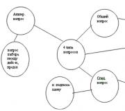
Inspection of utility networks includes 4 types of work:
Visual inspection and assessment of the technical condition of utility networks
This block of work includes a visual inspection design features building and its engineering systems. On at this stage specialists identify damage, on the basis of which a defective statement is formed. Staff and representatives of contractors are also interviewed to obtain the most objective data possible.
Checking the compliance of actual qualitative and quantitative parameters with those recommended for a given class and type of building
The second stage of work is carrying out a series of measurements to determine the key technical parameters, recording the examination results. The obtained data is compared with acceptable values, and violations are identified.
What parameters are checked for compliance with standards?
- indoor air temperature in summer - 23–25°C, in winter - 22–24°C;
- air humidity 40–60%;
- circulation of air masses 60 m 3 / h per 10 m2;
- air exchange in the workplace - 0.13–0.25 m/s;
- illumination - 300–500 lux;
- The noise level should not exceed 55 dB.
During audit The following measuring instruments are used:
- Thermal imager - helps to identify defects in the thermal protection of a building.
- Current electric clamp - measures current strength.
- Multimeter - measures voltage, resistance, current.
- Sound level meter - measures the noise level.
- Pyrometer - measures surface temperature.
- Anemometer - measures the speed of air flow in closed systems and on open area(measurement of air flow speed inside air ducts).
- PH meter - measures the level of hydrogen ions in the system.
- Luxmeter - measures the level of illumination of the workplace.
- A device for measuring CO2, temperature and air humidity.
Analysis/reconciliation of current technical documentation
The third block of work includes:
- checking the availability of correctly completed documentation (in accordance with the register of documents that regulates the activities of operating organizations);
- checking the availability of equipment documentation ( technical passports);
- checking compliance with safety regulations, as well as the availability of logs and their correct filling;
- analysis of concluded contracts with resource suppliers;
- diagnostics of metering devices.
Preparation of a detailed report with the results of the audit of engineering systems
On final stage a report is drawn up with conclusions on the fact of the comprehensive comprehensive inspections of utility networks.
The report consists of the following documents:
- conclusion with the inspection results and assessment of the technical condition of each of the engineering systems separately;
- defective statement with photographs and detailed description faults, with the timing and estimated cost of elimination;
- Conclusion with the results of measurements of premises parameters highlighting inconsistencies acceptable standards;
- reconciliation report on the presence/absence of mandatory executive and technical documentation at the site. Recommendations for the quality of maintaining operational logs;
- determination of compliance or non-compliance of engineering systems with requirements fire safety, electrical safety, sanitary-epidemiological and environmental standards;
- conclusion on the operation of metering devices and recommendations for reducing the cost of resource consumption.
During a comprehensive inspection of buildings, it is necessary to check the utility networks, which are the main elements of the facility. The inspection helps to make a realistic assessment of their technical condition, timely identify defects, damage and malfunction of elements of the overall system.
The technical condition is checked in accordance with VSN 58-88(r) “Regulations on the organization and implementation of reconstruction, repair and Maintenance buildings, municipal and socio-cultural facilities”, and the verification of physical deterioration is determined in accordance with the document VSN 53-86(r) “Rules for assessing the physical depreciation of residential buildings”.
In the case of previously carried out repairs or replacement of individual elements of the system, physical wear is determined according to certain tables as a weighted average value. Based on the final results of the inspection and determination of the technical condition of the system, a decision is made on further actions and the possibility of subsequent operation of utility networks.
Emergency situations with engineering systems, resulting in flooding of residential premises, arise for the following reasons:
- Poor quality installation of shut-off valves.
- The use of low-quality materials that do not have an appropriate quality certificate and warranty during pipeline installation.
- Moral and physical wear and tear of pipeline, heating and sewerage systems.
- The presence of defects in the overall system.
During the examination of the cause of the accident, the location of its occurrence is simultaneously determined. At this stage, an assessment is made of the technical condition of the shut-off valves and the general condition pipeline system. If during the inspection it turns out that the shut-off valves are destroyed, then an additional examination of its destroyed parts is carried out. Laboratory examination helps to determine the cause of destruction and the suitability of the material.
In case of emergency situation when putting the system into operation, after eliminating the consequences and eliminating the cause, a report is drawn up indicating the cause of the accident, location and total area damage.
After restoration work, a defective statement is drawn up, in which the following information is indicated and attached:
- location of the defect;
- the number of detected damages and their name;
- the cause of the defect;
- defects recorded in the photo;
- measuring the parameters of the damage caused and the humidity of the building structure;
- estimate for restoration work.
Our company has sufficient experience, tools and a highly qualified staff of experts who will help carry out a high-quality inspection of utility networks, draw up an appropriate report, a defective statement and make calculations on the amount of damage caused, as well as give recommendations for troubleshooting.
1. We conduct inspections of engineering systems in the following scope:
- Inspection of hot water supply systems - description DHW systems, pipeline inspection and circulation pumps, description of cooking technology hot water and used water heaters, carrying out instrumental measurements - temperature measurements, determining the thickness of corrosive deposits. Development of drawings with the application of pipelines and distribution of the hot water supply system on floor plans, indicating the diameters and linking them to existing structures.
- Inspection of heating and heat supply systems - inspection of the thermal input and central heating substations, description of the heating system and wiring diagrams of the supply and return lines, inspection of heating devices, temperature measurements, determination of the thickness of the narrowing of the live section of pipelines, drawing of the heating system on floor plans.
- Inspection of cold water supply systems - inspection of water supply to the building, inspection of the metering unit cold water and instrumentation, description of the water supply system, determination of the thickness of corrosion deposits in pipelines, drawing of the cold water supply system on plans with diameters indicated.
- Inspection of sewerage systems - inspection of pipelines and sanitary fixtures, inspection of ventilation risers and revisions, determination of the slope of horizontal pipelines, drawing of sewer risers and fixtures on floor plans.
- Inspection of ventilation systems - type determination ventilation system, inspection of ventilation ducts and ventilation equipment, determination of air exchange in the inspected rooms of the building, identification of defects and comparison with regulatory requirements.
- Inspection of waste disposal systems - inspection of waste collection chambers, establishing the integrity and tightness of the shaft, establishing compliance with the requirements of design and regulatory documentation.
- Inspection of gas supply systems - description design diagram gas supply systems, study of documentation for gas pipelines and equipment, determination of compliance of the gas pipeline system with design documentation.
- Inspection of the technical condition of drains - a description of the drainage system, reveals unacceptable damage - blockages, tightness of joints, the presence of grates and caps, the presence of an electric heating cable.
- Inspection of electrical networks and communications - description of the input distribution device, inspection of electrical cabinets on the floors, inspection lighting fixtures, inspection of low-current systems, drawing electrical panels and power supply wiring on building plans.
- Inspection of engineering equipment - the actual condition of the equipment used for various purposes is determined. Physical and moral wear and tear is determined in accordance with identified defects and malfunctions.


2. Composition of the technical report on the inspection of engineering systems and networks
1. Explanatory note - description of the surveyed engineering systems
2. Inspection of heating systems and heat supply of the building
- description of heating and heat supply systems
- drawing heating systems onto floor plans
- instrumental examination of heating and heat supply systems, defects, conclusions and recommendations
3. Inspection of building ventilation systems
- description of ventilation systems
- drawing ventilation systems onto floor plans
- instrumental examination of ventilation systems, defects, conclusions and recommendations
4. Inspection of water supply and fire extinguishing systems of the building
- description of water supply and fire extinguishing systems
- drawing water supply and fire extinguishing systems on floor plans
- instrumental examination of water supply and fire extinguishing systems, defects, conclusions and recommendations
5. Inspection of building drainage systems
- description of drainage systems
- drawing drainage systems on floor plans
- instrumental examination of drainage systems, defects, conclusions and recommendations
6. Inspection of building electrical systems
- description of power supply systems
- drawing electrical systems onto floor plans
- instrumental inspection of power supply systems, defects, conclusions and recommendations
7. Results of calculations of existing loads on the building, analysis of input nodes for the possibility of increasing loads, identification of places for possible connections of new networks
8. Conclusions based on the results of the inspection of the building’s engineering systems
10. Executive diagrams - plans with applied engineering systems
Inspection of the technical condition of engineering equipment systems is carried out during a comprehensive examination of the technical condition of buildings and structures.
The inspection of engineering equipment and its elements consists of determining the actual technical condition of systems, identifying defects, damage and malfunctions, quantifying physical and moral wear and tear, and identifying deviations from the design.
The assessment of the technical condition of engineering systems of buildings and structures is carried out taking into account the average standard service life of elements and engineering devices, determined.
Physical wear and tear of engineering equipment systems is determined in accordance with. Moreover, if during the process of reconstruction or operation some elements of the system were replaced with new ones, then the physical wear and tear is clarified by calculation and determined by the formula
where is the physical wear and tear of an element or system, %;
Physical wear of a section of an element or system, %, determined by ;
Dimensions (area or length) of the damaged area, miles m;
Dimensions of the entire structure, miles m;
Number of damaged areas.
The physical wear of the system is determined as the sum of the weighted average wear of the elements.
Obsolescence of engineering equipment systems is determined by the non-compliance of its operational qualities with modern regulatory requirements or the absence of any engineering equipment without the presence of a replacement for its functional purpose. Quantitative assessment of obsolescence is carried out by determining the cost of eliminating wear and tear as a percentage of the replacement cost of the building.
Indicators of obsolescence of residential buildings in the absence of certain types of engineering equipment, without the presence of a replacement for its functional purpose, are given in Appendix K.
During a detailed examination of heating systems, hot and cold water supply, an assessment of the corrosion condition of pipelines and heating devices. The corrosion state is assessed by the depth of maximum corrosion damage to the metal wall and by the average value of the narrowing of the pipe cross-section by corrosion-scale deposits in comparison with a new pipe.
In this case, samples are taken from the system elements (risers, connections to heating devices, heating devices). Based on the samples, the maximum depth of corrosion damage and the value of the narrowing of the “live” section are determined. When selecting and transporting cutting samples, it is necessary to ensure complete safety of corrosion deposits in the pipes (samples). Passports are prepared for the cut samples, which, together with the samples, are sent for laboratory examination.
The number of risers from which samples are taken must be at least three. When examining a system with embedded risers, samples for analysis are taken at the points where they are connected to the mains in the basement.
The number of connections from which samples are taken must be at least three, going from risers in different sections and to different heating devices.
The permissible value of the maximum relative depth of corrosion damage to pipes should be taken equal to 50% of the wall thickness of the new pipe.
The permissible value of pipeline narrowing due to corrosion-scale deposits should be taken in accordance with hydraulic calculations for pipes that have been in service (absolute roughness value - 0.75 mm).
Under these conditions, the permissible narrowing will be:
For pipes with 15 mm - 20%;
For pipes with 20 mm - 15%;
For pipes with 25 mm - 12%;
For pipes with 32 mm - 10%;
For pipes with 40 mm - 8%;
For pipes with 50 mm - 6%.
An acceptable narrowing of the “live” cross-section of convectors, subject to an acceptable reduction in the heat transfer of the heating device, should be considered 10%.
The relative depth of corrosion damage to the pipe metal, %, is estimated using the formula
where is the wall thickness of a new pipe according to GOST 3262 of the same diameter and type (light, ordinary, reinforced);
The minimum remaining thickness of the pipe wall after operation in the system by a specific date.
The narrowing of the open cross-section of the pipe, %, by products of corrosion-scale deposits is estimated using the formula
where is the average internal diameter of the pipe with deposits;
The inner diameter of the new pipe, taken according to GOST 3262 in accordance with its outer diameter.
The permissible value of pipeline narrowing due to corrosion-scale deposits is accepted with a reduction in the “live” cross-section of the pipe by no more than 30%, as a result of which the minimum free pressure value for sanitary fixtures is ensured.
5.4.1 Inspection of the technical condition of hot water supply systems
5.4.1.1 When inspecting the technical condition of hot water supply systems, the following work is guided and carried out:
Describe the system (type of system, piping diagram);
Inspect circulation pumps, instrumentation, shut-off and control valves at the entrance to the building or structure;
Inspect pipelines (in the basement, rooms, attic) and identify defects (fistulas in metal, drip leaks in places of threaded connections of pipelines and cut-in valves, traces of repairs of pipelines and mains, failure to warm up heated towel rails, corrosion damage to pipelines and heated towel rails, violation of the thermal insulation of main pipelines and risers), inspect the condition of pipeline fastenings and supports;
Instrumental measurements are carried out:
1) water temperature in the supply line and in the return pipeline (at the heating point of the building);
2) the temperature of the water supplied to the water supply (at the outlet of stage II water heaters or at the entrance to the building);
3) temperature of the circulating water (at the lower bases of the circulation risers);
4) temperature of drained water from water taps (in control rooms and risers of rooms farthest from heating point);
5) surface temperature of heated towel rails (in control rooms and risers of rooms furthest from the heating point);
6) free pressure at water taps (in the rooms on the top floor, the risers furthest from the heating point);
7) slopes of laying main pipelines and connections (in the basement and representative rooms).
5.4.1.2 Based on the survey results, the degree of compliance is determined.
5.4.2 Inspection of the technical condition of heating systems
5.4.2.1 When inspecting the technical condition of heating systems, the following work is guided and carried out:
Describe the system (type of system - centralized, local, one-pipe, two-pipe; wiring diagram of the supply and return lines, etc.);
Determine the types and brands of heating devices;
Inspect the most critical elements of the system (pumps, main shut-off valves, control and measuring equipment, automatic devices);
Inspect pipelines, heating devices, shut-off and control valves (in the basement, rooms, staircases, attic);
Establish deviations in the system from the design;
The following damage, malfunctions and defects are detected:
a) corrosion damage and fistulas of main pipelines, risers, connections, heating devices,
b) corrosion damage to embedded pipelines,
c) traces of repairs (clamps, patches, welding, replacement of individual sections, counter-slopes of distribution pipelines, drip leaks in places where shut-off and control valves are inserted, dismantling and breakdown of heating devices in staircases, in lobbies, failure of the heating system stairwells, vestibules, destruction or absence of thermal insulation in certain sections of pipelines;
The following instrumental measurements are carried out:
1) outside air temperature (in the building area),
2) water temperature in the supply pipeline of the heating network (at the heat input node or heat point before the mixing device or water heater or after the inlet valve),
3) water temperature in the return pipeline of the heating line (at the heat input unit or heat point in front of the inlet valve),
4) water temperature in the supply pipeline of the heating system (at the heat input unit or heat point after the mixing device, if available, or after the water heater with an independent heating system),
5) water temperature in the return pipeline of the heating system (at the heat input unit or heat point),
6) surface temperatures of heating risers at the upper and lower bases (on all risers),
7) surface temperature of heating devices (in representative rooms),
8) surface temperatures of supply and return connections heating devices(in representative premises),
9) air temperature in heated rooms (in representative rooms),
10) slopes of distribution pipelines,
11) pressure in the system: in the supply and return pipelines of the heating network (at the heat input unit or heat point), in the supply and return pipelines of the heating system.
5.4.2.2 Based on the survey results, the degree of compliance is established.
5.4.3 Inspection of the technical condition of cold water supply systems
5.4.3.1 When inspecting the technical condition of cold water supply systems, the following work is guided and carried out:
Describe a system (dead-end, ring), including: entrance to the building, water metering unit, distribution network, risers, connections to sanitary fixtures; water-folding, mixing and shut-off and control valves;
Inspect water supply inputs into the building and identify damage (deterioration of socket and welded joints of cast iron and steel pipelines under the influence of bending forces due to uneven settlement);
Inspect the adjacent area (lawn) and blind areas in the input zone (presence of sediment, dips, uncompacted soil);
Inspect the water metering unit and instrumentation; check the caliber and mesh of the water meter (in case of disturbances in the flow of water to the water supply points of the premises on the upper floors);
Inspect pumping installations;
Inspect pipelines, shut-off valves and taps, water meters and identify damage in the basement and premises (leaks in pipelines in places where taps and shut-off valves are inserted, damage to pipelines, traces of pipeline repairs, corrosion damage to pipelines, breakdown of shut-off valves and flush tanks);
The following instrumental measurements are carried out in the system:
1) pressure in the supply pipeline (at the input unit),
2) free pressure at water taps (in the rooms on the top floor furthest from the inlet in the risers).
5.4.3.2 Based on the survey results, the degree of compliance is established.
5.4.4 Inspection of the technical condition of sewerage systems
5.4.4.1 When inspecting the technical condition of sewerage systems, the following work is guided and carried out:
Inspect pipelines and sanitary fixtures in the premises and basement and identify defects (damage to pipelines, breakdown of socket and butt joints, drip leaks at the connection points of sanitary fixtures, traces of repairs and replacement of individual sections of pipelines);
Check the compliance of the routing of pipelines laid in the basement with the design solution;
Instrumentally measure the slopes of horizontal sections of pipelines in the basement in accordance with , the slope of horizontal sections and outlets must be at least 0.02, and the slopes of outlet sections from risers must be at least 0.05;
Carry out calculations (in case of constant flooding of the basement wastewater) the diameter of the pipeline outlet depending on the number of sanitary fixtures attached to it in accordance with;
The ventilation risers of the sewer network are inspected, taking into account that the protruding part of the risers is discharged through the roof or prefabricated ventilation shaft to the following height:
Projection diameter sewer riser must correspond to the diameter of the waste part of the sewer riser; The release of ventilation sewer risers into the cold attic is not allowed.
5.4.4.2 Based on the survey results, the degree of compliance is established.
5.4.5 Inspection of the technical condition of ventilation systems
5.4.5.1 When inspecting the technical condition of ventilation systems, the following work is guided and carried out:
Describe the design solution of the ventilation system (natural duct exhaust without organized air flow, mechanical duct supply and exhaust, smoke removal system with mechanical induction);
They examine the technical condition of the system elements and identify the following defects and malfunctions:
1) leakage of air ducts and pipes at the points of connection to ventilation units (indoors),
2) violation of the integrity (reduction of dimensions, dismantling) of ventilation units (in premises),
3) discrepancy between the cross-section of ventilation openings of air ducts and air distributors and the design solution (in premises),
4) leakage, violation of integrity and thermal insulation ventilation ducts and mines (cold attic),
5) violation of the integrity of the heads of ventilation units (diffusers), leakage of the warm attic, which is a prefabricated ventilation chamber,
6) mechanical damage to ventilation shafts and deflectors on the roof,
7) damage to the automatic devices of the smoke removal system,
8) damage to the mechanics of the supply and exhaust system (ventilation units, fans, valves, dampers);
Carry out instrumental measurements of air exhaust volumes (in all rooms);
Check ventilation and smoke ducts for permeability.
5.4.5.2 Based on the survey results, the degree of compliance is established.
5.4.6 Inspection of the technical condition of waste disposal systems
5.4.6.1 When inspecting the technical condition of waste disposal systems, they are guided by, conduct an inspection of the barrel, loading valves, gates, fire valves of the cleaning device, waste collection chambers with equipment, deflectors and identify the following defects and malfunctions:
1) violation of the integrity and tightness of the butt joints of the barrel;
2) looseness of the trunk;
3) leakage of loading valves;
4) absence or damage of metal parts of loading valves;
5) failure of the hopper with gates;
6) disruption or lack of cold and hot water supply in the waste collection chamber;
7) destruction of the lining and waterproofing of the floor in the garbage chamber;
8) violation of the tightness of the narthex and locking of the garbage chamber door;
9) leakage of the connection between the ventilation duct and the barrel;
10) absence or destruction of ventilation duct insulation in a cold attic.
5.4.6.2 Based on the survey results, the degree of compliance is established.
5.4.7 Inspection of the technical condition of gas supply systems
5.4.7.1 The gas supply system includes engineering devices for transporting gas to the combustion site, as well as its most efficient and safe use. Gas is burned in gas burners, the design of which depends on the purpose of the gas appliance ( gas stove, water heater, furnace, etc.). Combustion products of internal gas supply devices are removed by ventilation.
5.4.7.2 To assess the technical condition of the gas supply system, they are guided by GOST 21.609, GOST 21.610 and carry out the following work:
Describe the design diagram of the gas inlet into the building (external inlet, basement inlet, routing of the inlet through the technical basement, including from the looped intra-block network);
Study technical documentation for gas pipelines and gas equipment, which includes:
1) a situational plan of the household with a diagram of gas distribution and shut-off devices (plans for these communications are stored in specialized gas services),
2) lists of gas appliances indicating the premises where they are installed, the number and type of installations,
3) acts on the condition of gas ducts,
4) acts on major repairs of equipment,
5) passports of technical devices,
6) acts of acceptance of gas pipelines and gas equipment into operation,
7) certificates of acceptance tests and inspections carried out during the operation of gas pipelines and gas equipment,
8) acts, reports on work performed during major repairs and reconstruction of gas pipelines and gas equipment,
9) a set of design drawings indicating the main technical solutions and all changes made during the execution of the work and notes on the approval of these changes with the organization that developed the gas pipelines and gas equipment project,
10) acts of investigation of accidents and violations of technological processes affecting the safety of gas pipelines and gas equipment;
The inspection establishes compliance with the design of the existing gas supply system (laying gas pipelines, installing gas appliances, apparatus and other gas-using equipment);
Inspect the technical condition of pipelines and equipment and identify defects and malfunctions:
1) gas leaks and leaky connections of pipeline sections,
2) the presence of deformations in the pipelines that arose during the settlement of the building,
3) the absence of sleeves in places where pipelines pass through ceilings and walls (the sleeves must ensure free linear movements independent of building structures caused by temperature deformations of the gas pipeline),
4) breakdown of gas stoves, hot water heaters, etc.;
Check the operation of the ventilation system and flue ducts;
The technical condition of chimneys (gas ducts) is examined for permeability, density, isolation, and the presence of normal draft. The main reasons for disruption of the normal operation of chimneys are:
1) blockages of chimneys with construction waste, mortar, bricks from the collapse of pipe heads,
2) blockage with snow or ice plugs due to cooling of the walls of the head during severe frosts,
3) local narrowing of the chimney,
4) head location chimney in the zone of wind pressure,
5) leakage of chimneys.
5.4.8 Inspection of the technical condition of drains
5.4.8.1 When inspecting drainage devices, the following work is guided and carried out:
Describe the structural drainage system (external organized drainage, unorganized external drainage, internal drainage);
Inspect the technical condition of drainage devices and identify the following faults and damage:
1) corrosion, fistulas, holes and destruction of metal gutters, overhangs and drainpipes,
2) violation of the connections of individual elements of drainpipes,
3) the absence of individual elements of drainpipes and fastenings to external walls,
4) clogged drain pipes,
5) violation of waterproofing in places where the water inlet funnels of the internal drainage meet the roof,
6) violation of the tightness of butt joints along the internal drain riser,
7) clogging and icing of water intake funnels of internal drainage and open outlets,
8) violation of the thermal insulation of internal drain risers in a cold attic,
9) condensation humidification of the thermal insulation of internal drain risers in a cold attic,
10) lack of protective grilles and caps in the funnels of the internal drainage system.
5.4.8.2 If condensation and ice forms on the eaves and drainage devices, the attic is inspected and the following reasons for violations of the temperature and humidity conditions are established:
Destruction of the walls of ventilation ducts and ventilation shafts;
Destruction or lack of thermal insulation of utility pipelines;
Insufficient thickness of the attic floor insulation (determined by calculation);
Release of sewer or basement exhaust ducts into the attic volume;
Lack of tightness of the vestibules of attic entrance doors and hatches.
5.4.8.3 Based on the inspection, compliance with the requirements for the system of drainage devices is established in accordance with.