Soft start in Chinese power supplies. Family of “start-prof” programs for the design and calculation of the strength and rigidity of pipelines for various purposes
SOFT-Start for the amplifier.
This circuit allows for a smooth start of the amplifier power supply. During the first 2...3 seconds, the primary winding of the step-down transformer is connected to the network through two series-connected resistors with a nominal value of 22R and a power of 5W. This time is enough to charge the filtering electrolytic capacitors of the power supply unit. Next, these resistors are shunted by the relay contacts, and the transformer enters normal operation. The Soft-Start circuit diagram is shown below:

This circuit was reviewed on the cxem(net) forum, and it is there that it is explained how to calculate the limiting current, the formula is as follows:
I=220/R5+R6+Rt, where:
I – Limiting current;
220 – mains voltage;
R5, R6 – ratings of current-limiting resistors in Ohms;
Rt is the DC resistance of the transformer primary in Ohms.
When the values of resistors R5 and R6 are reduced to less than 15 Ohms, the efficiency of the device decreases; when using resistors with a nominal value of more than 33 Ohms, their heating increases, so it is better to stick to this range. Calculation example:
With R5=R6=22R and a primary resistance of 3 to 8R, the starting current will be equal to 220 / (22+22+3...8), that is, from 4.68 to 4.23 Amperes.
The delay time is controlled by the value of capacitor C3, located in the base circuit of transistor VT1; to increase the time, install a capacitor of larger capacity. Otherwise, no additional settings are required.
When drawing the board, I used the signet of Ilya Stelmakh, known on the forum under the nickname NemO, as a sample, I slightly adjusted it to suit my needs, the watering can looks like this:
Powerful resistors are soldered vertically into the board and connected to each other at their upper ends, thus creating a series connection.
List of Soft-Start Amplifier circuit elements:
Transistors:
VT1 – BD875 or BDX53 (composite) – 1 pc. (you can also use the domestic transistor KT972)
Diodes:
VDS1 – 1N4007 – 4 pcs.
VD1 – 1N5358B – Zener diode for 24V – 1 pc.
VD2 – 1N4148 – 1 pc.
Resistors:
R1 – 82k – 1 pc.
R2 – 220R / 2W – 1 pc.
R3 – 62k – 1 pc.
R4 – 6k8 – 1 pc.
R5, R6 – 22R / 5W – 2 pcs.
Capacitors:
C1 – 470nF / 400...630V – 1 pc.
C2 – 220mF / 25V – 1 pc.
C2 – 220mF / 16V – 1 pc.
Rest:
K1 – relay for voltage 12V / 30...40mA, contacts must be rated for current 5A or more.
Safety block + fuse – 1 pc. (the fuse rating depends on what transformer you use in the amplifier's power supply; to determine it, I used the formula taken from the NO CIRCUIT forum: Ip = (Pbp/220) * 1.5. The result must be rounded to the nearest standard value of the melting current)
Connector 2 Pin 5mm (220 IN, 220 OUT) – 2 pcs.
The size of the archive for downloading materials according to the Soft-Start scheme is 0.25 Mb.
START-Prof was put into commercial operation in 1969
Carrying out calculations using the START-Prof programs ensures reliability and safety during the operation of pipeline systems for various purposes, facilitates approval of the project with regulatory authorities (Rostechnadzor, Glavsgosexpertiza), and reduces costs and commissioning time.
START-Prof was developed by NTP Truboprovod LLC, an expert organization of Rostechnadzor. There is a certificate of conformity from the Federal Agency for Technical Regulation and Metrology.
START-Prof has an interface, documentation and help system in Russian, English and Chinese, used in more than 2000 companies in Russia, Ukraine, Kazakhstan, Belarus, Uzbekistan, China, Japan, Great Britain, Czech Republic, Latvia, Bulgaria, Germany and Finland. The total number of licenses exceeds 10,000.
An internal quality assurance system is used: each released version of START-Prof undergoes automatic testing on several hundred verification calculation models.
Provides high-quality and prompt support for user programs.
System requirements: Windows 7/8/10, IA-32 or AMD64/EM64T architecture processor, RAM 1GB or higher, video card supporting OpenGL 2.0 or higher (NVIDIA or AMD/ATI chipset, NVIDIA GeForce 7000 or higher or Radeon X300 is recommended or higher), display at least 1280x1024 or higher, with 1GB or more memory.
Standards for assessing strength and load-bearing capacity
The programs of the START-Prof family are designed to calculate the strength and rigidity of pipelines for various purposes, having an arbitrary configuration in space, under static and cyclic loading, under seismic influences, as well as the thickness of pipe walls and connecting parts for pressure:
- Steam and hot water according to RD 10-249-98, ASME B31.1 (USA), DL/T 5366-2014 (China);
- Heating networks in accordance with GOST R 55596-2013, RD 10-400-01 (the document is outdated), CJJ/T 81-2013 (China);
- Process pipelines for oil refining, chemical, petrochemical, gas and other industries in accordance with GOST 32388-2013 (instead of RTM 38.001-94 and SA 03-003-07), RTM 38.001-94 (outdated document), ASME B31.3 (USA), EN 13480-2017 (EC), GB/T 20801-2006, GB 50316-2008 (China);
- Main gas and oil pipelines in accordance with SNiP 2.05.06-85, SP 36.13330.2012, ASME B31.4-2016, ASME B31.8-2016 (USA), GB 50251-2015, GB 50253-2015 (China);
- Pipelines for various purposes made of fiberglass according to ISO 14692-3:2002/Cor 1:2005;
- Pipelines made of polymer materials HDPE, PP, PVC, PE-RT, PVDF, etc. according to GOST 32388-2013;
- Other types of pipelines: ASME B31.5-2016, ASME B31.9-2014 (USA);
- Designated service life of process pipelines in accordance with GOST 32388-2013 and heating networks in accordance with GOST R 55596-2013;
- Rejection thicknesses of pipes and connecting parts (bends, transitions, tees, plugs) of process pipelines in accordance with the requirements of GOST 32388-2013.
- Wind loads according to SP 20.13330.2016 (Russia), TKP EN 1991-1-4 2009 (Belarus), ASCE 7-16 (USA), EN 1991-1-4:2005+A1:2010 (Europe), GB 50009 ( China), IS.875.3.1987 (India), IBC 2012 (International), UBC 1997 (International), AZ/NZS 1170.2:2011 (New Zealand), NBC 2010 (Canada), NBR 06123-1988 (Brazil), BS 6399-2 (UK), CNS (Taiwan), NSR-10 (Colombia), CFE 2008 (Mexico)
- Snow loads according to SP 20.13330.2016 (Russia), ASCE 7-16 (USA), EN 1991-1-3:2003+A1:2015 (Europe), GB 50009-2012 (China), NBC 2010 (Canada);
- Ice loads according to SP 20.13330.2016 (Russia), ASCE 7-16 (USA), GB 50135-2006 (China);
- Seismic loads according to SNiP II-7-81* (Russia), SP 14.13330.2014 (Russia), NP-031-01 (Russia), GB 50011-2010 (China).
What pipelines does START-Prof calculate?
START-Prof tools are used to calculate both self-compensating pipelines, in which compensation for temperature expansion is ensured by the flexibility of the pipeline route itself, and pipelines with special compensating devices made in the form of bellows, lens, stuffing box and other types of compensators. Pipelines of almost any complexity are calculated:
- Aboveground, in a channel, pinched in the ground;
- Flat, arbitrary spatial, branched, with closed contours;
- With various designs of end and intermediate supports;
- Subject to various external influences (temperature expansion, concentrated and distributed loads, displacement of supports, pre-stretching, expansion from internal pressure, etc.);
- Operating at low (cryogenic), medium and high temperatures (the effect of creep and stress relaxation is taken into account according to the standards);
- From various materials: steel, non-ferrous metals, fiberglass, plastic;
- With internal excess pressure both up to and above 10 MPa, as well as with external excess pressure (vacuum) - for such areas, the local stability of the walls is checked;
- It is possible to calculate several unrelated pipelines in one file.
Database
START-Prof has a number of regulatory databases that provide additional convenience when working:
- “Materials” – contains the physical properties of pipe materials and pipeline elements;
- “Springs” – contains the characteristics and compliance of spring chains of elastic supports of various load capacities according to OST 108.764.01-80, OST 24.125.109-01, MVN 049-63, MN 3958-62, LISEGA, WITZENMANN, NBT 47039-2013, China power , ANVIL, Pipe Supports Ltd., Carpenter & Paterson Ltd, SEONGHWA;
- “Constant Force Fastenings” – contains the characteristics of constant force fastenings WITZENMANN, NB/T 47038-2013, ANVIL, Pipe Supports Ltd., Carpenter & Paterson Ltd, SEONGHWA;
- “Soils” – contains various physical and mechanical properties of soils;
- “Compensators” – contains characteristics of axial, angular, shear bellows and lens compensators from various manufacturers;
- “Insulation” – contains insulation weight values depending on the insulating structure, temperature and pipe diameter;
- “Bends”, “Tees”, “Transitions” - contains product characteristics for various industries.
Composition and additional options
Available in four modifications, differing in price and capabilities:
- START-Prof - for professionals solving large-scale problems, as well as for calculating long pipelines pinched in the ground (with the START-Grunt option);
- START-Prof Economy – budget version with restrictions;
- START-Prof Student – a lightweight version of the program intended for educational purposes (supplied only to educational institutions);
- START-Express is an inexpensive product designed for preliminary simplified calculations at the pipeline design stage.
All modifications have equal capabilities in terms of preparing initial data and analyzing calculation results, which provides great convenience for their simultaneous use in local computer networks. Modifications differ in the maximum permissible number of degrees of freedom.
| Modification START-Prof | Minimum program configuration |
Available quantity degrees of freedom |
Approximate maximum length pipeline for channelless installation in the ground L, m* |
START-Prof |
START-Prof |
||
START-Prof Economy |
START-Prof Economy |
||
START-Prof Student |
START-Prof Student |
||
START-Prof All inclusive |
START-Prof + START-Grunt + START-Seismic + START-Assigned resource + START-Nozzle + START-Open format + START-Foreign standards + START-Plastic + START-PDMS + START-DB Products |
*Note D – outer diameter, mm
The START-Prof program allows you to perform calculations of pipelines of any configuration, but without sections of channelless installation in the ground. This opportunity appears with the START-Ground option.
The START-Prof and START-Prof Economy programs can be equipped with additional options:
- "START-Grunt" - allows you to calculate a pipeline with sections pinched in the ground (channelless installation), as well as evaluate the strength of polyurethane foam and polymineral foam insulation.
- "START-Seismics" - allows you to calculate pipelines for seismic impacts (only for above-ground pipelines, using the static method).
- “START-Assigned resource” – calculation of the assigned resource of the designed process pipelines, taking into account cyclic strength and corrosive wear in accordance with RTM 38.001-94, GOST 32388-2013 and GOST R 55596-2013.
- “START-Fitting” – calculation of the compliance (rigidity) of the pipeline insertion unit into vessels (devices). It is possible to automatically generate and insert a non-standard fastener into START.
- “START-Plastik” – Calculation of pipelines for various purposes made of fiberglass according to ISO 14692-3:2002. Calculation of pipelines made of polymer materials PE, PP, PB, PVC according to GOST 32388-2013. Calculate strength under internal pressure and determine support loads for flexible polymer pipes and corrugated steel pipes. The option can be connected to START-Prof and START-Prof Economy.
- “START-Foreign Standards” – Calculation of pipelines according to foreign regulatory documents: China, USA, as well as imports from the Caesar II program.
- “START-PDMS” – two-way data exchange with the AVEVA PDMS program when working with PDMS and START on one PC.
- “START-Open format” – import of input data from an open format, export of input data and calculation results into an open format for connecting the START program with any computer-aided pipeline design systems. An open format is a text file of a certain structure.
- "START-DB Products" - database of bends, tees, transitions. The option cannot be connected to START-Prof Economy.
Additional options are supplied only together with the main module (START-Prof Economy, START-Prof or START-Prof Student).
Calculation of dimensions of a U-shaped compensator in START-Express
START-Express – pipeline designer tool
The program is designed to quickly assess the compensating capacity of individual sections of the pipeline route, checking their strength and stability. During the design process, piping designers must constantly solve similar problems. Using START-Express you can determine:
- compensating ability of L-, Z-shaped and U-shaped expansion joints when laying pipelines above the ground and in underground channels;
- compensating ability of L-, Z-shaped and U-shaped compensators for channelless laying of pipelines in the ground;
- wall thickness or maximum pressure for pipes, bends, tees, plugs, transitions in accordance with the selected regulatory document;
- distances between intermediate pipeline supports based on strength and rigidity conditions;
- general and local stability of straight and curved sections of pipes under the influence of thermal expansion, external pressure (vacuum) and soil pressure (for channelless pipes);
- minimum laying depth for sections of channelless laying based on stability conditions;
- the maximum laying depth for sections of channelless laying based on the strength of polyurethane foam insulation;
- maximum permissible distances between START compensators and their closure temperature for pipelines pinched in the ground;
- permissible load on the saddle support for large diameter pipes;
- tightness of flange connections;
- rigidity of bellows expansion joints in the absence of data from the manufacturer.
Calculation of L-, Z-shaped and U-shaped expansion joints when laying pipelines above the ground and in underground channels is carried out for sections located between two fixed (dead) supports. With a known distance between the fixed supports, the required reach for a U-shaped compensator, a Z-shaped turn and a short arm for an L-shaped turn are determined based on the permissible compensation stresses. This eliminates the need for designers to use outdated nomograms for L-, Z- and U-shaped sections.
Calculation of L-, Z-shaped turns and U-shaped compensators for channelless laying of pipelines in the ground allows, based on a given overhang for a U-shaped compensator or Z-shaped turn and the length of the short arm of the L-shaped turn, to determine the permissible distance between fixed supports, then is the length of a section of a pipeline pinched in the ground that can be compensated for a given temperature difference. U-shaped compensators and L- and Z-shaped turns with arbitrary angles are considered. For the same pipeline sections, you can perform a verification calculation - for given dimensions, determine the stresses, displacements and loads on fixed supports.
START-Prof is:
- clear and intuitive user interface;
- convenient and well-thought-out object-oriented method of inputting initial data;
- comprehensive logical check of the quality of the initial data for the calculation;
- detailed help system and software documentation;
- automatic checking of all pipeline parts for internal pressure;
- checking and selecting parameters of typical pipeline units (various types of expansion joints, tie-ins, tees, flange connections);
- the ability to calculate pipelines for various purposes and locations (including vacuum pipelines) according to various regulatory documents;
- calculation of the compliance of fittings of vessels and apparatus for a more accurate calculation of loads on fittings and stresses in the pipeline;
- integration with various three-dimensional design systems for industrial installations, the Shtutser-FEM program, export of design diagrams to various graphical environments (AutoCAD, MicroStation, KOMPAS-Graph);
- import geometry from the “Hydraulics” program;
- regular (once every 1-2 months) advanced training courses for program users;
- a wide, established network of distributors throughout Russia, in the CIS countries and abroad;
- constant technical support from developers.
Calculation capabilities
- Accounting for friction in sliding, guide, elastic and other supports;
- Taking into account the interaction of the pipeline with the soil in areas of channelless installation. The nonlinear compliance of the soil, the layer of polyurethane foam insulation and shock-absorbing cushions is taken into account. Variable depth and arbitrary angle of inclination of sections are taken into account;
- Assessment of the strength of polyurethane foam insulation;
- Automatic selection of springs for elastic supports and suspensions, calculation of their tightening;
- Automatic accounting of the “gauge effect” in bends with initial ovality and thrust forces from internal pressure throughout the pipeline;
- Taking into account the pendulum effect when the rods of rigid and elastic suspensions deviate from the vertical position;
- Taking into account one-way connections (for example, lifting a pipeline above supports);
- Accounting for the joint operation of the pipeline with equipment (module “START-Fitting”);
- Taking into account the work of elastically curved sections of large radius;
- Checking the stability of the walls of vacuum pipelines, the possibility of taking into account reinforcement with stiffening rings of various configurations;
- Based on the calculation results, tables of stresses are displayed in accordance with the selected regulatory document, loads on supports, displacements, forces, deformations of compensators, stability coefficients of the walls of the vacuum pipeline;
- Graphic illustration of the deformed state in various design states of the pipeline;
- Graphic color illustration of the fulfillment of regulatory strength criteria on a pipeline diagram.
START-Prof is your right choice!
Today START-Prof is one of the most widespread software systems for calculating the strength and rigidity of pipelines for various purposes in Russia and the CIS countries. The software system has reached the level of a kind of industrial standard and in its consumer properties is not inferior to foreign analogues. Users of the program are design organizations in the chemical, gas, energy and a number of other industries. The program has been widely used in the design, construction and reconstruction of heating networks.
The START-Prof software system (PS) has a long history, spanning more than 40 years. The first edition of the program - then it was called ST-01 - was put into commercial operation back in 1969. For eight years, the system was successfully operated on “Minsk” series computers, then on ES series computers, and since 1992 on personal computers – first under DOS and then under Windows. The change of generations of computers and operating systems, as a rule, was accompanied by a major overhaul, while the capabilities of the software were constantly expanded, and the user interface and calculation algorithm were polished and improved.
Thanks to the huge number of users and constant feedback from specialists in various industries, the START-Prof software system is verified in detail, including through cross-testing with similar domestic and foreign programs, and is constantly being developed.
All programs of the START-Prof family have a certificate from the State Standard of Russia issued by TsSPS LLC.
Users of the START-Prof software system
The list below is by no means complete. Currently, START-Prof is used in more than 1,500 organizations, including:
Thermal power engineering and heat supply. Regional engineering centers and generating energy companies: Institute "Teploelektroproekt", ICE Ural, ICE Povolzhye, JSC "Association VNIPIenergoprom", BelNIPIEnergoprom, Atomenergoproekt (Moscow), Atomenergoproekt (Nizhny Novgorod), Zarubezhenergoproekt, SibCOTES, Siberian ENTC, Teploproekt, EK, Mosinzhproekt , TVEL-Teploross Corporation, MosFlowline, SPKB RR OJSC Mosenergo, Mosteploenergo, Moscow Heating Network Company, TsNIIEP Dwellings, Kanalstroyproekt. China: Beijing deyu technical service, Jinan Municipal Engineering Design & Research Institute, Qingdao Kaiyuan Heating Engineering Design and Research Institute, Jilin Gas And Heating Engineering Design Institute, Institute of Architecture Design & Research, China Academy of Sciences, Beijing Thermal Engineering Design, Shenyang Thermal Engineering Design and Research Institute, Heilongjiang Academy of Forestry Research and Design Institute, Heilongjiang Haote Thermal Design, China Northeast Municipal, Yinchuan planning & design institute, Estonia: OU Aither, Lithuania: UAB Bioprojektas, Gandras Ebergoefektas
Once upon a time, when LED light sources were not so popular and compact fluorescent lamps were expensive and unreliable, the simplest solution was incandescent lighting. Now it’s the other way around - LED lamps are installed almost everywhere, and LNs have become exotic. But they are still irreplaceable in some places and will not go out of use completely soon. Unfortunately, frequent switching on and off, as well as current fluctuations, lead to bulb burnouts. To increase their service life, a simple version of the incandescent lamp slow start circuit was used.
Turning on groups of lamps through a soft start system will also reduce the impact of a current surge on the network, which will reduce the risk of overcurrent protection tripping. A very simple soft start system can be performed using the U2008B chip.
Soft start circuit for lighting
So, in order to extend the life of 220V incandescent lamps, it is worth using a soft start system. The soft start system, when you turn on an incandescent lamp or a group of lamps, will gradually increase their power, which will prevent current shocks that occur when the lamp coil is cold. The cold coil of 100 W incandescent lamps has a resistance of about 40 ohms, which at 220 V corresponds to a power of 1.2 kW.
 Wiring diagram of the soft start module on the U2008B chip
 When implementing a soft start, the power adjustment function with a potentiometer will not be used, and only the soft start system will work. The system contains elements that allow, if necessary, to connect a potentiometer to manually adjust the power. This schematic solution greatly simplifies the design, eliminating the need to use microcontrollers and programs for them.
Description of the system operation
The power rise time depends on the capacitance of capacitor C3, for 1 µF we get a fast start, for 4.7 µF a standard soft start, for 10 µF a smooth soft start. Here the capacitance selected is 10 µF.
We connect the incoming power to the lamps to connectors J1 and J2, and connect the lamps themselves to connectors J3, J4, marked LOAD in the diagram. Screw connections were used for connections.
When controlling 200W lamps, a radiator for the thyristor is not required.
The device is assembled on a small board and is located in a junction box.
Attention: 220 V mains voltage is dangerous to life and health. Special care must be taken when starting the circuit. The administration does not bear any responsibility for the result of working with network voltage; you do everything at your own peril and risk!
The system is suitable for conventional 220 V incandescent lamps, as well as halogen lamps operating directly from the mains power supply. But the circuit is not suitable for light sources with electronic power systems and transformers.
Bottom Line
The device has been operating for many years, and the service life of incandescent lamps has noticeably increased (several times). This system can also extend the life of popular halogen lamps with E27 base.
 A simple power reduction circuit using a triac
 You can set the power limit (for example, by half), as part of savings, which will provide sufficient illumination of utility rooms and provide an easier operating mode. The simplified module diagram is above. Over 10 years of operation with 5 incandescent lamps in a chandelier (5x100W), the triac was replaced only once. The light bulbs themselves still shine properly at 80% power.
The requirement for standby and soft start options is usually considered appropriate in expensive models. They are unjustifiably considered an object to satisfy the whims of a wealthy buyer. This is not entirely true, or rather, not true at all. It is rather a tool for extending the life of expensive lamps and maintaining their stable properties for a long time.
Translated into commonly understood language, standby is a readiness mode, a standby mode until called upon. That is, the lamps are in a mode of either reduced current extraction, or the voltage at the anode is reduced against the working voltage and, therefore, cathode wear is minimized. Thus, the life of the lamps is extended by the time during which they were heated and aged “for free.” In addition, it becomes possible to almost instantly switch the amplifier into operating mode - the music will flow immediately, after pressing a button or clicking a toggle switch.
Soft start (ss) - a smooth start, the moment of soft switching on of the amplifier, guaranteeing non-emergency modes of all its elements. The afterburner of the heating of the lamps, the impact on the rectifier, the power transformer and the power supply network itself are eliminated. SS is designed to increase the reliability of the entire device not only when turned on, but also to extend the life of wear elements.
In addition to the obvious reasons, such as excess power on the anode and grids, overheating of the filament with a voltage higher than the normalized one, supplying an unacceptably high anode or a primitive misunderstanding when pulling the lamp out of the socket, you can point out five more non-obvious reasons for lamp failure.
1. The most common cause of lamp death is the filament burning out when full filament voltage is applied to it. An inrush of current due to the fact that the resistance of the cold filament is 5-7 times less than the heated one, if it does not immediately “kill” the lamp, it will significantly reduce its resource due to cyclic forced heating. In the end, the lamp will “have a heart attack” somewhere along the way when it is working honestly.
2. Lack of current collection at full operating temperature is fraught with poisoning of the cathode. Between the nickel core and the oxide, a layer of barium silicate is formed, which has high thermal and ohmic resistance. Naturally, emissions decrease. In addition, due to the uneven thickness of this layer, electrons fly out from areas of the emitting surface at different speeds. This increases the shot noise caused by the unequal number of electrons leaving the cathode per unit time.
3. The vacuum in the cylinder is not absolute; it contains residual molecules and gas atoms that were not removed during evacuation. In addition, new ones appear due to the fact that the elements inside the cylinder, and the glass itself, “float”. At the moment the anode voltage appears before emission begins, random electrons, pulled out by a powerful electrostatic field, bombard these molecules and ionize them. Accelerated ions rush to the surface of the cathode and “break through” its emitting surface with a thickness of 1-2 atoms. These holes reduce the effective surface of the cathode and, accordingly, its emissivity decreases. For signal lamps, this process is noted through an increase in noise level (flickering or flicker noise by nature, not to be confused with shot noise!), for powerful lamps - through “balding” of the cathode and loss of emission. The getter partially neutralizes the remaining gases and to a greater extent when the cathode is heated before the anode voltage is applied. The getter is more effective when it is hot.
4. Incorrect orientation of the lamp in space (sounds like the orientation of a spaceship!). If this is fundamentally unacceptable for directly incandescent lamps, then for indirectly incandescent lamps it is necessary to avoid their horizontal installation. In this case, the mesh (other meshes) may sag when heated and come into contact with it. cathode or anode. In both cases, lamp failure is inevitable. Even if it is not forbidden to install the lamp in any way, the golden rule is one thing: it must stand vertically! With tubes turned upside down (in some guitar amplifiers), there is a chance that the mastic connecting the cylinder to the base will come off. It is not uncommon for a situation when the temperature of the lamp is such that the solder in the pins melts and the cylinder, not held in place by anything, falls off.
5. Dust, dirt, fingerprints on the cylinder, poorly designed radiators - all this reduces the degree of radiation emission and leads to overheating of the anode. To some extent, dirt provokes the formation of areas on the surface of hot glass where it softens and the cylinder “collapses”. However, these are all banalities known to anyone who has at least once looked into a book with the theory of electric vacuum devices. It seems like a simple matter, you just have to hold the anode supply while the filament and cathode are slowly heating up, and when a visible cherry glow of the filament appears, click the switch and - it's in the bag. No matter how it is!
Firstly: you are too lazy to wait every time you turn on the music, otherwise you lose all the thrill of an instantly fulfilled desire. This is not a haymower with its levers, pedals and buttons, and therefore the discipline of the operator (what a foreign word, just right for a haymower!) of the machine is simply abhorrent to many.
Scheme 1. Limiting the filament current when turning on Scheme 2. Reducing the filament voltage when turning on Secondly: fascinating crimson (ruby, ocher, straw or ripe watermelon, depending depending on the type of lamp and color perception) you still need to see the dots. What if the amplifier is designed to be closed? You won’t stand there with a stopwatch, right? Or, with your heart pounding, count down the agonizing seconds, wish they would fly by faster.
Thirdly: if it is not you who turns on, but, say, your friend. Then your explanations can ruin your mood not only for the evening, but forever. She will certainly consider you a bore, go to the driver, and do the right thing.
Fourth: even if you manually delay the supply of anode voltage, you still turn on the filament voltage with a click and then - see point 1 of non-obvious reasons for failure. This means we need automation.
Automation for soft-start"a
First of all, this means including a current-limiting element in the filament circuit. The simplest implementation will be circuits 1, 2, 3. Although in this case the shock current will still be there, albeit reduced in amplitude.

If there are free contacts on the executive relay, you can turn on the LEDs indicating the current mode of the device. If you use an LED with a built-in multivibrator, the warm-up time will be signaled by red and green lights alternately.
If it makes sense to power the filament with direct current, using a voltage stabilizer, then you can get by with circuit 5. The power of the microcircuit will depend on the total current consumption and the power dissipated on its body. Our 5 or 6 volt Kren, LM7805, LM78MD5, placed on a radiator, will do just fine.
The executive relay receives a control signal from the timer. Usually this is 1006VI1 or NE555. The time constant is determined by the product RC. Common practice is to use R up to 1 MΩ and capacitor value up to 100 µF. You should not be zealous in increasing R, since the leakage current of the timer input may be higher than the capacitor charging current. And so that the leakage current of the capacitor does not confuse the cards, I advise you to use either a good electrolyte (tantalum, niobium, oxide semiconductor are quite suitable for this purpose; do not be embarrassed, here they do not affect the sound), or film ones. Type K73 will be the best choice (lavsan dielectric). The holding time will be 0.6-0.75 T and will depend on your requirements, although there is no point in delaying it for more than 1-1.5 minutes (Scheme 4).

Automation for standby
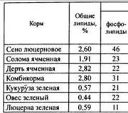
Finnish engineer and author of many articles Jukka Tolonen presented in one of the issues of GA the results of experiments reflecting the readiness time of the circuit depending on the heating voltage applied to the filament.
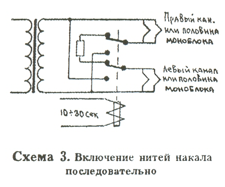
Scheme 3. Switching on the filaments accordingly
From the table it can be seen that if the warm-up voltage is more than 2.5 V, then the sound will appear after switching almost instantly (see table). Other authors recommend raising the warm-up voltage to 4 V, and also using this value for standby mode, so that there is no poisoning of the cathode when fully heated in the absence of anode current. The magnitude of the resistance, as well as its power, should be selected experimentally. If 2.5-4 volts drops when the glow is fully warmed up, then the resistor connected in series with it will continue to act as a damper when turned on.
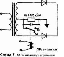
Similar solutions can be used to delay the anode voltage, but note that in this case a relay with high-voltage contacts is required (Fig. 7, 8).

The issue of smooth startup of the entire circuit in f amplifiers was solved in an original way. Audio Research Ml00, M300, V70, etc. The main dampers here are thermistors connected to the primary winding circuit of the power transformer. When warmed up, their resistance decreases, then is completely bypassed by the relay contacts (diagram 6). In general, Audio Research automation is an example of how issues of reliability and safety need to be addressed.

Automation for standby
The simplest solutions can be implemented using a toggle switch, the contacts of which can withstand high voltages and high currents. True, you will have to turn it on manually. However, it is quite acceptable to use a relay.
Simple and reliable
The most democratic schemes are those with a kenotron. In the sense that the process of warming it up naturally slows down the readiness time. If the current demands of the amplification circuit are large, say, 300-500 mA per channel, then 5Ts8S, 5Ts9S - our killer kenotrons - are suitable. For an appetite of up to 300 tA, 5Ts4S/5S4M and damper diodes 6D20P, 6D22S will do (see diagram 14). The last two are especially suitable in anode voltage rectifiers, since they are fast and have high emissivity.

What is good about Kenotron? Until it warms up, the anode power will not reach the lamps of the circuit, and by that time the lamps themselves will be ready for operation. Plus, there is no shock charging current when turned on if you install the kenotron as a damper immediately after the rectifier. But not after the filter! See diagram 15.

Everything is nice, the anode supply occurs as smoothly as possible, and with one click of the network switch, such “automation” works more reliably than anything. However, in return we have three troubles: 1) the incandescent dampers eat up current and not a small one, at worst - as much as 5 Amperes! 2) dampers consume not only current, but also voltage. The drop across a vacuum diode depends on the current through it and the parallelism of the halves. In a kenotron (two-node) they should be connected in parallel, and not only to reduce the internal resistance, but also to unload the thermal regime of the lamp. So, here you can lose 20-50 volts**. This means that a voltage reserve on the power trance should be provided, or such “clumsy grace” should be abandoned, for example, by shunting the kenotron. At the same time, do not forget to turn off its heat! (Diagram 16). Keep in mind that if all the windings are on one power transformer, then it promises to turn into an iron and “sag” to indecent output voltage values. After all, no matter how thick the wires are used to wind the incandescent windings, the current in the primary will do its job and the voltage actually applied in the primary winding will be noticeably lower than 220 V. For this case, taps are provided in the primary in order to somehow compensate for this decrease. Trouble No. 3: kenotrons are also lamps and their resource is limited. They will require replacement if the emission becomes noticeably weaker, although this is still cheaper than replacing the output (and input) lamps.
There is one more problem that is not difficult to overcome: when using direct-heat kenotrons with alternating current power supply to the filament, the problem of anode current fluctuations arises. This occurs due to low thermal inertia, when the filament manages to heat up and cool down twice during the period; The emission fluctuates with the same frequency, and therefore the anode current will fluctuate. The treatment of this disease is shown in Fig. (Diagram 17). More details about this in the book by V.F. Vlasov “Electrovacuum Devices” for 49, p. 129.

But, if you have finally decided to fly to the Sun and, in the words of V. Khlebnikov, “notorious Suvorov,” spit on silicon and dampers, install directly heated kenotrons. Of the fairly powerful ones, 5TsZS remains. Outdated VO-183 (analogous to RCA83, which is very popular), German-Hungarian AZ, EZ series, as well as mercury ones - these are for gourmets. I'm not looking for a special sound in them. So, in "Ongaku" from gourmets, the gourmet - Hiroyasu Kondo - used 5AR4, connected by a bridge, to obtain 960 V from a transformer with two windings of 360 V each. Naturally, this cannot be achieved using a circuit with a midpoint, otherwise one would have to use either a circuit multiplication, or at the cost of using indirectly heated kenotrons. But what about the purity of the idea? It turns out that you can give up your principles a little if you really want to. What I mean is that I don’t see much sense in the direct heat of kenotrons (Diagram 18).

I use silicon diodes and a vacuum damper. In front of it I place another small capacitance of 4-10 uF type MBGCh or paper in oil (KBG-MN, etc.) and think (possibly erroneously) that this helps the sound. I explain by the fact that this linearizes the transmission characteristic of the diode, since the range of changes in the current through it decreases (ripples are attenuated by the capacitor), and secondly, an extra filtering link appears, in the form of a fairly linear and almost active resistor (vacuum diode with a low internal), which It’s a sin not to use the I-filter scheme. If, at the same time, it is high-speed, like a damper diode for horizontal scanning, then problems with emissions at the discharge edge do not arise. When rectified only by semiconductors, even if they are high-speed, like HEX FRED, the emissions, although attenuated by the filter elements, still fall on the anodes of the lamps in the form of broadband interference. This technique can already be considered as a struggle for nutrition for the sake of nutrition, so let it become a separate story. Finally, as a living example, the implementation of automation in the PROTOTYPE amplifier presented at the RHE "99 exhibition. Its author is A. Pugachevsky.
Cx. 19. Scheme of automatic softstart and standby in the “Prototype” amplifier. Simplified version

We did not set ourselves the task of providing a complete, comprehensive Soft start and Standby scheme suitable for all occasions. In addition, some solutions were left out, covering which is quite time-consuming, but they provide little benefit. So let everyone choose a solution according to their taste and ability. It’s worth paying attention to this: cramming in more automation is not an end in itself. This will not change subjective assessments of the sound of the device much, but it (automation) is an indicator of the manufacturer’s care for the buyer. So that, after a while, he does not have headaches and, accordingly, you.
The soft start circuit provides a delay of about 2 seconds, which allows you to smoothly charge larger capacitors without voltage surges and blinking light bulbs at home. The charge current is limited by: I=220/R5+R6+Rt.
where Rt is the resistance of the primary winding of the transformer to direct current, Ohm.
The resistance of resistors R5, R6 can be taken from 15 Ohms to 33 Ohms. Less is not effective, but more increases the heating of the resistors. With the ratings indicated in the diagram, the maximum starting current will be limited, approximately: I=220/44+(3…8)=4.2…4.2A.
The main questions that beginners have when assembling:
1. At what voltage should the electrolytes be set?
The voltage of the electrolytes is indicated on the printed circuit board - these are 16 and 25V.
2. At what voltage should I set a non-polar capacitor?
Its voltage is also indicated on the printed circuit board - it is 630V (400V is allowed).
3. What transistors can be used instead of BD875?
KT972 with any letter index or BDX53.
4. Is it possible to use a non-composite transistor instead of BD875?
It’s possible, but it’s better to look for a composite transistor.
5. What relay should be used?
The relay must have a 12V coil with a current of no more than 40mA, and preferably 30mA. Contacts must be designed for a current of at least 5A.
6. How to increase the delay time?
To do this, it is necessary to increase the capacitance of capacitor C3.
7. Is it possible to use a relay with a different coil voltage, for example 24V?
It’s impossible, the scheme won’t work.
8. Assembled - does not work
So it's your mistake. A circuit assembled using serviceable parts starts working immediately and does not require configuration or selection of elements.
9. There is a fuse on the board, what current should it be used for?