Electricity meter symbol on the diagram. Symbols in GOST electrical diagrams
If you are engaged in electrical installation work, then you definitely need to know the symbols in electrical circuits. The ability to read electrical diagrams is an important quality for fitters, instrumentation mechanics, and circuit designers. And if you do not have special training, it is unlikely that you will be able to immediately understand all the intricacies. But we must remember that the symbols on the diagrams that are being developed for Russian consumers differ from generally accepted standards abroad - in Europe, the USA, and Japan.
History of designations on diagrams
Back in the Soviet years, when electrical engineering was developing rapidly, the need arose to classify devices and their designation. It was then that the Unified System of Design Documentation (ESKD) and state standards (GOST) appeared. Everything was standardized so that any engineer could read the symbols on the drawings of his colleagues.
But in order to understand all the intricacies, you will need to listen to many lectures and study a lot of specialized literature. GOST is a huge document, and it is almost impossible to fully study all the graphic symbols and their standard sizes and notes. Therefore, it is necessary to always have a small “cheat sheet” on hand that will help you navigate the variety of electrical components.
Electrical wiring on drawings
Electrical wiring is a general concept; it refers to conductors that have very low resistance. With their help, voltage is transmitted from the source of electricity to consumers. This is a general concept as there are many types of electrical wiring.
People who do not understand electrical wiring diagrams and features may think that a conductor is an insulated cable that connects to switches and sockets. But in fact, there are many types of conductors, and they are designated differently on diagrams.
Conductors on diagrams

Even copper tracks on PCB circuit boards are a conductor; one might even say that this is a variant of electrical wiring. Indicated on electrical diagrams as a straight connecting line passing from one element to another. In the same way, the electrical wires of a high-voltage line laid in the fields between the poles are indicated on the diagram. And in apartments, the connecting wires between lamps, switches and sockets are also indicated by straight connecting lines.
But the designations of conductive elements can be divided into three subgroups:
- Wires.
- Cables.
- Electrical connections.
Electrical wiring plan is an incorrect definition, since electrical wiring refers to both installation wires and cables. But if you significantly expand the list of elements, as is necessary in the detailed diagram, it turns out that it is necessary to include also transformers, circuit breakers, residual current devices, grounding, and insulators.
Sockets on diagrams

Sockets are plug connections designed for non-rigid connection (there is the possibility of manually breaking the connection) of electrical circuits. Symbols on the drawings are strictly regulated by GOST. With its help, rules are established for designating lighting devices and devices and various other electrical consumers on drawings. Plug-type sockets can be divided into three categories:
- Designed for outdoor installation.
- Designed for hidden installation.
- A block that includes a socket and a switch.
- Single pole sockets.
- Bipolar.
- Bipolar and safety contact.
- Three-pole.
- Three-pole and protective contact.
That's enough, the sockets have no special features, there are many design options. All devices have a degree of protection; the choice must be made based on the conditions in which they will be used: humidity level, temperature, presence of mechanical stress.
Switches on wiring diagrams

Switches are devices that break an electrical circuit. This can be done automatically or manually. The conventional graphic designation is regulated by GOST, as with sockets. The designation depends on the conditions in which the element operates, what design it has, and the degree of protection. There are several types of switch designs:
- Single-pole (including double and triple).
- Bipolar.
- Three-pole.
The diagrams must indicate the parameters of the disconnecting device. And the graphic designation shows which type is used: simple with or without fixation, an acoustic device (responsive to cotton) or optical. If you want the lights to turn on at nightfall and turn off in the morning, you can use an optical sensor and a small control circuit.
Fuses (fuse links)

There are many types of protection devices - fuses (disposable and self-restoring). Many types of design, scope of application, different response speeds, reliability, use in certain conditions characterize these devices. The symbol for a fuse is a rectangle; the simplest and cheapest element that can protect an electrical circuit from a short circuit runs parallel to the long side through the center. It should be noted that such components are quite rarely used in electrical circuit diagrams. Another type of symbol can be found - these are self-resetting fuses, which, after opening the circuit, return to their original state.
The broad name for fuses is fuse link. It is used in many devices, in electrical distribution panels. You can find them in disposable corks. But there are also devices used in high-voltage systems. They are structurally made of metal tips and a main ceramic part. Inside there is a piece of conductor (its cross-section is selected depending on the maximum current that should flow through the circuit). The ceramic body is filled with sand to prevent the possibility of ignition.
Circuit breakers

The symbols for devices of this type depend on the design and degree of protection. The reusable device can be used as a simple switch. In essence, it performs the functions of a fuse-link, but it is possible to return it to its original state - to close the circuit. The structure consists of the following elements:
- Plastic case.
- Lever for turning on and off.
- Bimetallic plate - when heated, it deforms.
- Contact group - it is included in the electrical circuit.
- Arc chamber - allows you to get rid of the formation of sparks and arcs during a connection break.
These are the elements that make up any circuit breaker. But you need to remember that after triggering it will not be able to immediately return to its original position; time must pass for it to cool down. The service life of machines is measured in the number of operations and ranges from 30,000-60,000.
Grounding on diagrams

Grounding is the connection of the current conductors of an electric machine or device to the ground. In this case, both the ground and part of the device circuit have a negative potential. Thanks to grounding, if the case breaks down, there will be no damage to the device or electric shock; the entire charge will go into the ground. Grounding is of the following types according to GOST:
- General concept of grounding.
- Pure grounding (noise-free).
- Protective type of grounding.
- Connection to the ground (body) of the device.
Depending on which grounding is used in the circuit, the symbol will be different. When drawing up diagrams, the drawing of the element plays an important role; it depends both on the specific section of the circuit and on the type of device.
If we are talking about automotive equipment, then there will be a “ground” - a common conductor connected to the body. In the case of home electrical wiring, these are conductors driven into the ground and connected to sockets. In logic circuits, one should not confuse “digital” grounding and conventional one - these are different things and they work differently.
Electric motors

Electric motors can often be found on electrical circuit diagrams of cars, workshops, and devices. Moreover, in industry, more than 95% of all motors used are asynchronous with a squirrel-cage rotor. They are designated in the form of a circle, to which three wires (phases) fit. Such electric machines are used in conjunction with buttons (“Start”, “Stop”, “Reverse” if necessary).
DC motors are used in automotive technology and control systems. They have two windings - working and excitation. Instead of the latter, permanent magnets are used on some types of motors. A magnetic field is created using the excitation winding. It pushes the motor rotor, which has a counter-directional field - it is created by the winding.
Wire color coding

In the case of single-phase power, the conductor with the phase is black, gray, purple, pink, red, orange, turquoise, white. Most often you can find brown. This marking is generally accepted and is used when drawing up diagrams and installation. is marked:
- Blue color - zero worker (N).
- Yellow with a green stripe - grounding, protection (PE) wire.
- Yellow with green and blue marks on the edges - the protective and neutral conductors are combined.
It should be noted that blue marks must be applied during installation. The symbol in electrical diagrams must also have a reference to the presence of marks. The conductor must be marked with the index PEN.
According to their functional purpose, all conductors are divided as follows:
- Black wires - for switching power circuits.
- Red wires - for connections of control, measurement, alarm elements.
- Blue conductors - control, measurement and signaling when operating on direct current.
- Zero working conductors are marked in blue.
- Yellow and green are wires for grounding and protection.
Alphanumeric designations on diagrams
The terminals have the following symbols in electrical diagrams:
- U, V, W - wiring phases;
- N - neutral conductor;
- E - grounding;
- PE - protective circuit wire;
- TE - conductor for silent connection;
- MM - conductor connected to the body (ground);
- CC - equipotential conductor.
Designation on wire diagrams:
- L - letter designation (general) of any phase;
- L1, L2, L3 - 1st, 2nd and 3rd phases, respectively;
- N - neutral wire.
In DC circuits:
- L+ and L- - positive and negative poles;
- M - middle conductor.
These are the symbols most often used in diagrams and drawings. They can be found in descriptions of simple devices. If you need to read the diagram of a complex device, you will need a lot of knowledge. After all, there are also active elements, passive elements, logic devices, semiconductor components and many others. And each has its own designation on the diagrams.
UGO winding elements

There are many devices that convert electrical current. These are inductor coils. The symbol of a transformer in the diagrams is two coils (depicted as three semicircles) and a core (usually in the form of a straight line). A straight line indicates a transformer steel core. But there may be transformer designs that do not have a core, in which case there is nothing on the diagram between the coils. This symbolic designation of elements can also be found in circuits of radio receiving equipment, for example.
In recent years, transformer steel has been used less and less in technology for the manufacture of transformers. It is very heavy, it is difficult to insert the plates into the core, and there is a buzzing sound when loosened. The use of ferromagnetic cores is much more effective. They are solid and have the same permeability in all areas. But they have one drawback - the difficulty of repair, since disassembling and reassembling turns out to be problematic. The symbol for a transformer with such a core is practically no different from the one in which steel is used.
Conclusion

These are not all the symbols of electrical circuits; the dimensions of the components are also regulated by GOST. Even simple arrows and connection points have requirements; their drawing is carried out strictly according to the rules. You need to pay attention to one feature - the differences in circuits made according to domestic standards and imported ones. The intersection of conductors on foreign diagrams is indicated by a semicircle. There is also such a thing as a sketch - this is an image of something without complying with GOST requirements for elements. Separate requirements apply to the sketch itself. Such images can be made to visually represent the future design and electrical wiring. Subsequently, a drawing is drawn up from it, in which even the symbols of conventional cables and connections comply with the standards.
To understand what exactly is shown on a diagram or drawing, you need to know the decoding of the icons that are on it. This recognition is also called blueprint reading. And to make this task easier, almost all elements have their own symbols. Almost, because the standards have not been updated for a long time and some elements are drawn by everyone as best they can. But, for the most part, symbols in electrical diagrams are in regulatory documents.
Symbols in electrical circuits: lamps, transformers, measuring instruments, basic components
Normative base
There are about a dozen varieties of electrical circuits, the number of different elements that can be found there is in the tens, if not hundreds. To make it easier to recognize these elements, uniform symbols have been introduced in electrical circuits. All rules are prescribed in GOSTs. There are many of these standards, but the main information is in the following standards:

Studying GOSTs is useful, but it requires time, which not everyone has enough of. Therefore, in the article we will present symbols in electrical circuits - the basic element base for creating drawings and wiring diagrams, circuit diagrams of devices.
Some experts, after carefully looking at the diagram, can say what it is and how it works. Some can even immediately indicate possible problems that may arise during operation. It’s simple - they know the circuit design and element base well, and are also well versed in the symbols of circuit elements. This skill takes years to develop, but for dummies, it’s important to remember the most common ones first.

Electrical panels, cabinets, boxes
On the electrical supply diagrams of a house or apartment there will definitely be a symbol or cabinet. In apartments, the terminal device is mainly installed there, since the wiring does not go further. In houses, they can design the installation of an electrical branch cabinet - if there is a route from it to illuminate other buildings located at some distance from the house - a bathhouse, a guest house. These other symbols are in the next picture.

If we talk about images of the “filling” of electrical panels, it is also standardized. There are symbols for RCDs, circuit breakers, buttons, current and voltage transformers and some other elements. They are shown in the following table (the table has two pages, scroll by clicking on the word “Next”)
| Number | Name | Image on the diagram |
|---|---|---|
| 1 | Circuit breaker (automatic) |  |
| 2 | Switch (load switch) |  |
| 3 | Thermal relay (overheat protection) |  |
| 4 | RCD (residual current device) |  |
| 5 | Differential automatic (difavtomat) |  |
| 6 | Fuse | |
| 7 | Switch (switch) with fuse |  |
| 8 | Circuit breaker with built-in thermal relay (for motor protection) |  |
| 9 | Current transformer |  |
| 10 | Voltage transformer |  |
| 11 | Electricity meter |  |
| 12 | A frequency converter |  |
| 13 | Button with automatic opening of contacts after pressing |  |
| 14 | Button with contact opening when pressed again |  |
| 15 | A button with a special switch to turn off (stop, for example) |  |
Element base for electrical wiring diagrams
When drawing up or reading a diagram, the designations of wires, terminals, grounding, zero, etc. are also useful. This is something that a novice electrician simply needs, or in order to understand what is shown in the drawing and in what sequence its elements are connected.
| Number | Name | Designation of electrical elements on diagrams |
|---|---|---|
| 1 | Phase conductor |  |
| 2 | Neutral (zero working) N |  |
| 3 | Protective conductor (ground) PE |  |
| 4 | Combined protective and neutral conductors PEN |  |
| 5 | Electrical communication line, buses | |
| 6 | Bus (if it needs to be allocated) |  |
| 7 | Busbar taps (made by soldering) |  |
An example of the use of the above graphic images is in the following diagram. Thanks to the letter designations, everything is clear even without graphics, but duplication of information in diagrams has never been superfluous.

Picture of sockets
The wiring diagram should indicate the installation locations of sockets and switches. There are many types of sockets - 220 V, 380 V, hidden and open installation types, with a different number of “seats”, waterproof, etc. To give a designation for each is too long and unnecessary. It is important to remember how the main groups are depicted, and the number of contact groups is determined by the strokes.

Designation of sockets in the drawings
Sockets for a single-phase 220 V network are indicated on the diagrams in the form of a semicircle with one or more segments sticking up. The number of segments is the number of sockets on one body (illustration in the photo below). If only one plug can be plugged into the socket, one segment is drawn upward, if two, two, etc.

If you look at the images closely, notice that the reference image on the right does not have a horizontal line that separates the two parts of the icon. This line indicates that the socket is concealed, that is, it is necessary to make a hole in the wall for it, install a socket box, etc. The option on the right is for open mounting. A non-conductive substrate is attached to the wall, and the socket itself is on it.
Also note that the bottom of the left diagram has a vertical line through it. This indicates the presence of a protective contact to which grounding is connected. Installation of sockets with grounding is mandatory when turning on complex household appliances such as a washing machine, oven, etc.

You won’t confuse the symbol for a three-phase socket (380 V) with anything else. The number of segments sticking up is equal to the number of conductors that are connected to this device - three phases, zero and ground. Total five.
It happens that the lower part of the image is painted black (dark). This means that the outlet is waterproof. These are placed outdoors, in rooms with high humidity (baths, swimming pools, etc.).
Switch Display
The schematic designation of switches looks like a small circle with one or more L- or T-shaped branches. Taps in the shape of the letter “G” indicate an open-mounted circuit breaker, while those in the shape of the letter “T” indicate a flush-mounted switch. The number of taps displays the number of keys on this device.

In addition to the usual ones, they can stand - to be able to turn on/off one light source from several points. Two letters “G” are added to the same small circle on opposite sides. This is how a single-key pass-through switch is designated.

Unlike conventional switches, when using two-key models, another bar is added parallel to the top one.
Lamps and fixtures
Lamps have their own designations. Moreover, there is a difference between fluorescent lamps and incandescent lamps. The diagrams even show the shape and dimensions of the lamps. In this case, you just need to remember what each type of lamp looks like on the diagram.

Radioelements
When reading circuit diagrams of devices, you need to know the symbols of diodes, resistors, and other similar elements.

Knowledge of conventional graphic elements will help you read almost any diagram - any device or electrical wiring. The values of the required parts are sometimes indicated next to the image, but in large multi-element circuits they are written in a separate table. It contains letter designations of circuit elements and denominations.
Letter designations
In addition to the fact that the elements on the diagrams have conventional graphic names, they have letter designations, which are also standardized (GOST 7624-55).
| Electrical circuit element name | Letter designation | |
|---|---|---|
| 1 | Switch, controller, switch | IN |
| 2 | Electric generator | G |
| 3 | Diode | D |
| 4 | Rectifier | VP |
| 5 | Sound alarm (bell, siren) | Sv |
| 6 | Button | Kn |
| 7 | Incandescent lamp | L |
| 8 | Electrical engine | M |
| 9 | Fuse | Etc |
| 10 | Contactor, magnetic starter | TO |
| 11 | Relay | R |
| 12 | Transformer (autotransformer) | Tr |
| 13 | Plug connector | Sh |
| 14 | Electromagnet | Em |
| 15 | Resistor | R |
| 16 | Capacitor | WITH |
| 17 | Inductor | L |
| 18 | Control button | Ku |
| 19 | Terminal switch | Kv |
| 20 | Throttle | dr |
| 21 | Telephone | T |
| 22 | Microphone | Mk |
| 23 | Speaker | Gr |
| 24 | Battery (voltaic cell) | B |
| 25 | Main engine | Dg |
| 26 | Cooling pump motor | Before |
Please note that in most cases Russian letters are used, but the resistor, capacitor and inductor are designated by Latin letters.
There is one subtlety in the designation of the relay. They come in different types and are marked accordingly:
- current relay - RT;
- power - RM;
- voltage - RN;
- time - RV;
- resistance - RS;
- index - RU;
- intermediate - RP;
- gas - RG;
- with time delay - RTV.
Basically, these are only the most conventional symbols in electrical circuits. But you can now understand most of the drawings and plans. If you need to know images of rarer elements, study GOST standards.
An electrical diagram is a type of technical drawing that identifies various electrical components in the form of symbols. Each element is assigned its own designation.
All conventional (symbolic-graphic) symbols on electrical diagrams consist of simple geometric shapes and lines. These are circles, squares, rectangles, triangles, simple lines, dotted lines, etc. The designation of each electrical element consists of a graphic part and an alphanumeric part.
Thanks to the huge number of different electrical elements, it becomes possible to create very detailed electrical circuits that are understandable to almost every specialist in the electrical field.
Each element on the electrical circuit must be made in accordance with GOST. Those. In addition to the correct display of the graphic image on the electrical diagram, all standard dimensions of each element, line thickness, etc. must be maintained.
There are several main types of electrical circuits. This is a single-line, schematic, installation diagram (connection diagram). There are also general types of diagrams - structural, functional. Each type has its own purpose. The same element on different diagrams can be designated both the same and differently.
The main purpose of a single-line diagram is a graphical display of the electrical power system (power supply of a facility, electrical distribution in an apartment, etc.). Simply put, a single-line diagram depicts the power part of an electrical installation. As the name suggests, a single-line diagram is made in the form of a single line. Those. Electrical power (both single-phase and three-phase) supplied to each consumer is indicated by a single line.
To indicate the number of phases, special ticks are used on the graphic line. One notch means that the power supply is single-phase, three notches indicate that the power supply is three-phase.
In addition to the single line, designations of protective and switching devices are used. The first devices include high-voltage circuit breakers (oil, air, SF6, vacuum), circuit breakers, residual current devices, differential circuit breakers, fuses, load switches. The latter include disconnectors, contactors, and magnetic starters.

High-voltage switches on single-line diagrams are depicted as small squares. As for circuit breakers, RCDs, differential circuit breakers, contactors, starters and other protective and switching equipment, they are depicted in the form of a contact and some explanatory graphic additions, depending on the device.
The installation diagram (connection diagram, connection, location) is used for the direct execution of electrical work. Those. These are working drawings, using which the installation and connection of electrical equipment is carried out. Also, individual electrical devices (electrical cabinets, electrical panels, control panels, etc.) are assembled according to the wiring diagrams.

Wiring diagrams show all wire connections both between individual devices (circuit breakers, starters, etc.) and between different types of electrical equipment (electrical cabinets, panels, etc.). To ensure the correct connection of wire connections, the wiring diagram shows electrical terminal blocks, terminals of electrical devices, brand and cross-section of electrical cables, numbering and letter designation of individual wires.
An electrical circuit diagram is the most complete diagram with all electrical elements, connections, letter designations, technical characteristics of devices and equipment. Other electrical diagrams (installation diagrams, single-line diagrams, equipment layout diagrams, etc.) are carried out according to the schematic diagram. The circuit diagram shows both the control circuits and the power section.

Control circuits (operational circuits) are buttons, fuses, coils of starters or contactors, contacts of intermediate and other relays, contacts of starters and contactors, phase (voltage) control relays, as well as connections between these and other elements.
The power part depicts circuit breakers, power contacts of starters and contactors, electric motors, etc.
In addition to the graphic image itself, each element of the diagram is provided with an alphanumeric designation. For example, a circuit breaker in a power circuit is designated QF. If there are several machines, each one is assigned its own number: QF1, QF2, QF3 etc. The coil (winding) of the starter and contactor is designated KM. If there are several of them, the numbering is similar to the numbering of machines: KM1, KM2, KM3 etc.

In each circuit diagram, if there is any relay, then at least one blocking contact of this relay is necessarily used. If the circuit contains an intermediate relay KL1, two contacts of which are used in operational circuits, then each contact receives its own number. The number always starts with the number of the relay itself, and then comes the serial number of the contact. In this case, we get KL1.1 and KL1.2. The designations for block contacts of other relays, starters, contactors, automatic machines, etc. are carried out in the same way.
In electrical circuit diagrams, in addition to electrical elements, electronic symbols are very often used. These are resistors, capacitors, diodes, LEDs, transistors, thyristors and other elements. Each electronic element on the diagram also has its own alphabetic and numerical designation. For example, a resistor is R (R1, R2, R3...). Capacitor – C (C1, C2, C3...) and so on for each element.
In addition to graphic and alphanumeric designations, technical characteristics are indicated on some electrical elements. For example, for a circuit breaker this is the rated current in amperes, and the cut-off current is also in amperes. For an electric motor, the power is indicated in kilowatts.
To correctly and accurately draw up electrical circuits of any type, you need to know the designations of the elements used, state standards, and documentation rules.
Almost all UOS, all radio electronics and electrical products manufactured by industrial organizations and enterprises, home craftsmen, young technicians and radio amateurs, contain a certain amount of various purchased electronic components and elements produced mainly by domestic industry. But recently there has been a tendency to use electronic components and components of foreign production. These include, first of all, PPPs, capacitors, resistors, transformers, chokes, electrical connectors, batteries, HIT, switches, installation products and some other types of electronic devices.
The purchased components used or self-manufactured electrical electronic components are necessarily reflected in the circuit and installation electrical diagrams of devices, in drawings and other technical documentation, which are carried out in accordance with the requirements of ESKD standards.
Particular attention is paid to electrical circuit diagrams, which determine not only the basic electrical parameters, but also all the elements included in the device and the electrical connections between them. To understand and read electrical circuit diagrams, you must carefully familiarize yourself with the elements and components included in them, know exactly the scope of application and the principle of operation of the device in question. As a rule, information about the electrical electronic equipment used is indicated in reference books and specifications - a list of these elements.
The connection between the list of ERE components and their graphic symbols is carried out through positional designations.
To construct conventional graphic symbols of ERE, standardized geometric symbols are used, each of which is used separately or in combination with others. Moreover, the meaning of each geometric image in a symbol in many cases depends on what other geometric symbol it is used in combination with.
The standardized and most frequently used graphic symbols of ERE in electrical circuit diagrams are shown in Fig. 1. 1. These designations apply to all components of the circuits, including electrical components, conductors and connections between them. And here the condition for the correct designation of the same type of electronic components and products becomes of utmost importance. For this purpose, positional designations are used, a mandatory part of which is the letter designation of the type of element, the type of its design and the digital designation of the ERE number. The diagrams also use an additional part of the ERE position designation, indicating the function of the element, in the form of a letter. The main types of letter designations for circuit elements are given in Table. 1.1.
Designations on drawings and diagrams of elements of general use refer to qualification ones, establishing the type of current and voltage. type of connection, control methods, pulse shape, type of modulation, electrical connections, direction of current transmission, signal, energy flow, etc.
Currently, the population and the trading network are using a significant number of various electronic instruments and devices, radio and television equipment, which are manufactured by foreign companies and various joint-stock companies. In stores you can purchase various types of ERI and ERI with foreign designations. In table 1. 2 provides information about the most common ERE of foreign countries with the corresponding designations and their domestically produced analogues.
This is the first time this information has been published in such a volume.
1- pnp structure transistor in a housing, general designation;
2- transistor of n-p-n structure in the housing, general designation,
3 - field-effect transistor with p-n junction and n channel,
4 - field-effect transistor with p-n junction and p channel,
5 - unijunction transistor with n-type base, b1, b2 - base terminals, e - emitter terminal,
6 - photodiode,
7 - rectifier diode,
8 - zener diode (avalanche rectifier diode) one-sided,
9 - thermal-electric diode,
10 - diode dinistor, lockable in the opposite direction;
11 - zener diode (diodolavin rectifier) with bidirectional conductivity,
12 - triode thyristor;
13 - photoresistor;
14 - variable resistor, rheostat, general designation,
15 - variable resistor,
16 - variable resistor with taps,
17 - trimming resistor-potentiometer;
18 - thermistor with positive temperature coefficient of direct heating (heating),
19 - varistor;
20 - constant capacitor, general designation;
21 - polarized constant capacitor;
22 - oxide polarized electrolytic capacitor, general designation;
23 - constant resistor, general designation;
24 - constant resistor with a rated power of 0.05 W;
25 - constant resistor with a rated power of 0.125 W,
26 - constant resistor with a rated power of 0.25 W,
27 - constant resistor with a rated power of 0.5 W,
28 - constant resistor with a rated power of 1 W,
29 - constant resistor with a rated dissipation power of 2 W,
30 - constant resistor with a rated dissipation power of 5 W;
31 - constant resistor with one symmetrical additional tap;
32 - constant resistor with one asymmetrical additional tap;
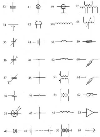
Fig 1.1 Symbols of graphical symbols of electrical power in electrical, radio and automation circuits
33 - non-polarized oxide capacitor;
34 - feed-through capacitor (the arc indicates the housing, the external electrode);
35 - variable capacitor (arrow indicates rotor);
36 - trimming capacitor, general designation;
37 - varicond;
38 - noise suppression capacitor;
39 - LED;
40 - tunnel diode;
41 - incandescent lighting and signal lamp;
42 - electric bell;
43 - galvanic or battery element;
44 - electrical communication line with one branch;
45 - electrical communication line with two branches;
46 - a group of wires connected to one electrical connection point. Two wires;
47 - four wires connected to one electrical connection point;
48 - battery made of galvanic cells or rechargeable battery;
49 - coaxial cable. The screen is connected to the body;
50 - winding of a transformer, autotransformer, choke, magnetic amplifier;
51 - working winding of the magnetic amplifier;
52 - control winding of the magnetic amplifier;
53 - transformer without a core (magnetic core) with permanent connection (the dots indicate the beginning of the windings);
54 - transformer with a magnetodielectric core;
55 - inductor, choke without magnetic circuit;
56 - single-phase transformer with a ferromagnetic magnetic core and a screen between the windings;
57 - single-phase three-winding transformer with a ferromagnetic magnetic core with a tap in the secondary winding;
58 - single-phase autotransformer with voltage regulation;
59 - fuse;
60 - fuse switch;
61 - fuse-disconnector;
62 - detachable contact connection;
63 - amplifier (the direction of signal transmission is indicated by the top of the triangle on the horizontal communication line);
64 - detachable contact connection pin;

Fig 1.1 Symbols of graphical symbols of electronic electrical power in electrical, radio and automation circuits
65 - detachable contact connection socket,
66 - contact for removable connection, for example using a clamp
67 - contact of a permanent connection, for example, made by soldering
68 - single-pole push-button switch with self-resetting closing contact
69 - switching device contact, general designation
70 - closing contact of the switching device (switch, relay), general designation. Single pole switch.
71 - switching device contact, general designation. Single pole double throw switch.
72- three-position switching contact with neutral position
73 - normally open contact without self-return
74 - push-button switch with normally open contact
75 - push-button pull-out switch with normally open contact
76 - push-button switch with button return,
77 - push-button pull-out switch with normally open contact
78 - push-button switch with return by pressing the button a second time,
79 - electric relay with normally open and switching contacts,
80 - relay polarized for one direction of current in a winding with a neutral position
81 - relay polarized for both directions of current in a winding with a neutral position
82 - electrothermal relay without self-reset, with return by pressing the button again,
83 - detachable single-pole connection
84 - socket of five-wire contact connector
85 - pin of contact detachable coaxial connection
86 - contact connection socket
87 - four-wire connection pin
88 - four-wire connection socket
89 - jumper switching breaking circuit
Table 1.1. Letter designations of circuit elements

Continuation of Table 1.1