Homemade CNC milling machine: assemble it yourself. Is it possible to make a CNC machine with your own hands? Homemade CNC milling machine from plywood drawings
The topic is quite specific, but I’ve been meaning to post something like this for a long time short review, and they often ask in messages.
I will give a list of the main components for homemade CNC machines: milling cutters, printers, engravers, etc., using the example of a homemade mini-milling machine
I have long been interested in the topic of CNC and related information and monitor the cost of “desktop” machines on the market, for example, CNC1610 or CNC2418. There have already been a couple of reviews on the first one (reviews on the CNC1610 from and from ). There has not been a review of the CNC2418 here yet; reviews on other resources are not encouraging. If anything, the numbers in the title are work zone machine Although, knowing my Chinese comrades, this is more likely the size of the machine.
Well, seriously speaking, the market value of such assembly kits is greatly inflated. I'm not ready to pay under $300 for such a set. But assembling it with your own hands is three times cheaper - please! For comparison, the photo on the left is CNC1610, on the right is CNC2418. They like to attach an additional laser head to the latter. 
By the way, to have a similar desktop CNC machine that will always be “on call” during production printed circuit boards and small crafts, this is a big plus for home handyman.
So, at one time I was puzzled by the assembly, and even assembled . Now I’m assembling from profile 2020. The set of components is approximately the same for both plywood and CNC2418. I will try not to miss anything and give full list components. 
As a rule, you need to buy a set of guides: rails or polished shafts, lead screws (most often T8, belts like GT2-6 can be installed in laser machines, but not in a milling cutter), Nema17 motors, spindle (most often a DC motor like RS775 or more powerful) and various small things such as bearings, calipers, hardware. The issue of electronics is separate: some use Arduino Nano/Uno+CNC Shield boards, others Mega+Ramps, there are options for more serious kits for Mach3.
I quote prices from Banguuda, because I’m tired of buying 1 lot from different sellers from Ali and waiting for a bunch of parcels arriving in different time. The prices are comparable to Ali, in some places it’s cheaper, in others it’s more convenient to use. As a result, I received one large parcel with a complete set. I also provide keywords for your own search if you need to find something similar on Ali or Tao.
Now, in order. I received a parcel of various components for machine mechanics. 
Guide shafts polished.
Linear Shaft (Rod). Still found Optical Axis(polished axis). There are 5-6-8-10-12-16-20 mm. Current diameter 8 mm. At 16-20 mm it is better to use round rails like SBR16 or SBR20, as they have support. Shafts different diameters used, for example, in the Ultimaker printer (6-8-10 mm). 12mm shafts - in the Z axis for the ZAV 3D printer.
In the photo 6 mm, 8 mm, 12 mm. 
Shafts 8 mm. I took some to size (they are chamfered), and cut some myself 
There are shafts from 5 mm to 12 mm and lengths 300-600 mm 
Individual lots are a little cheaper. I try to take the length either the same size or much larger, so that I can independently cut 2-3 pieces of the required size from one shaft. 
Here is the cut with a miter saw. It is advisable to then clean and chamfer. 
with lengths 300...500 mm
with lengths 100… 350 mm
Comfortable if you choose the right size. And from time to time they offer promotions for different lots; if you don’t rush to assemble the machine, you can save money.
Lead screw T8 ( Lead Screw T8, screw T8 Nut)
Considered in detail in, a screw with a multi-start thread. It's better to take it right away with the nut. 
If you cut, you will additionally need to buy more brass nuts
(pay attention to which warehouse in the store you choose, the price is different).
from 100 to 600 mm
I usually take more, plus one nut. I cut it to size, the rest goes somewhere else 
T8 screw on the end surface ( Flange Bearing KFL08)
T8 screw on profile Mount Bearing KP08

Profile components
2020 Corner Bracket
To assemble a type 2418 machine, a minimum of 16 pieces are required. Take with reserve))) 
for profile 2020 (8mm slot) 100 pcs. It’s also better not to waste time on trifles. A hundred pieces will fly apart in a moment, especially considering that they can be used to attach anything to a profile. To order: T Nut M4 (available M3, M5, for 6 mm groove) 
And here is the 2020 profile itself. It is structural. This is probably the most cheap option, since a profile from China will cost more, and there is a limitation on maximum length parcels by Chinese post (500mm).
I immediately bought a profile kit for 2418 cut to size.
Under the spoiler there are cut sizes and tips for ordering.
There are two options - an uncoated profile (cheaper) and a coated profile (anodized). The difference in cost is small, I recommend coated ones, especially if used as guides for rollers. 
Choose desired type profile 2020, then enter “cut to size”. Otherwise, you can buy one piece (whip) per 4 meters. When calculating, keep in mind that the cost of one cut varies depending on the profile. And that 4 mm is allowed for the cut. 
Enter the sizes of the segments. I made the 2418 machine a little larger, these are seven sections of 260 mm and two vertical sections of 300 mm. The vertical one can be made smaller. If you need a longer machine, then two longitudinal sections are larger, for example, 350 mm, and transverse sections are also 260 mm (5 pieces). 
We confirm (must be added to the cutting map) 
I usually take the leftovers (small pieces) for something else, for example, a holder for a 3D printer spool. 
The profile is obtained for 667 rubles together with the cutting service. 
Delivery is carried out by TK, you can calculate the cost using a calculator, since you know the profile dimensions, the weight is very well calculated in the cutting chart. Plus “collection of cargo from the supplier.” That is, the cost to me to Tula was 1450 (30 kg of profile for various purposes). Delivery Business lines It will cost less, about 1000 rubles.
You can pick it up in Moscow. 
In one place there is an office, a warehouse and a workshop where profiles are cut to size. There is a showcase with samples, you can evaluate the profile. I was just choosing a profile for the SBR20, it has seats every 30 mm, this is a profile, 3060, 3090. Initially I wanted 4040, I rummaged through the assortment, I realized that even 6060 is better.
But the profile is “in place” 
A separate topic is about the large machine.
Well, maybe I forgot to mention the spindle. The specified machines 1610 and 2418 use
This is my first CNC machine assembled with my own hands from available materials. The cost of the machine is about $170.
I have been dreaming of assembling a CNC machine for a long time. I mainly need it for cutting plywood and plastic, cutting some parts for modeling, homemade products and other machines. My hands itched to assemble the machine for almost two years, during which time I collected parts, electronics and knowledge.
The machine is budget, its cost is minimal. In what follows I will use words that to an ordinary person may seem very scary and this may scare you away from building a machine yourself, but in fact it is all very simple and can be easily mastered in a few days.
Electronics assembled on Arduino + GRBL firmware
The mechanics are the simplest, a frame made of 10mm plywood + 8mm screws and bolts, linear guides made of a metal angle 25*25*3 mm + bearings 8*7*22 mm. The Z axis moves on an M8 stud, and the X and Y axes on T2.5 belts.
The CNC spindle is homemade, assembled from a brushless motor and collet clamp+ toothed belt drive. It should be noted that the spindle motor is powered from the main 24 volt power supply. IN technical specifications The motor is stated to be 80 amps, but in reality it consumes 4 amps under heavy load. I can’t explain why this happens, but the motor works great and does its job.

Initially, the Z axis was on homemade linear guides made from angles and bearings, later I remade it, photos and description below.

The working space is approximately 45 cm in X and 33 cm in Y, 4 cm in Z. Taking into account the first experience, I will make the next machine with larger dimensions and will install two motors on the X axis, one on each side. This is due to the large arm and the load on it, when work is carried out at the maximum distance along the Y axis. Now there is only one motor and this leads to distortion of the parts, the circle turns out to be a bit elliptical due to the resulting flexion of the carriage along the X.

The original bearings on the motor quickly became loose because they were not designed for lateral load, and this is serious. Therefore, I installed two large bearings with a diameter of 8 mm on the top and bottom of the axle, this should have been done right away, now there is vibration because of this.

Here in the photo you can see that the Z axis is already on other linear guides, the description will be below.


The guides themselves are very simple design, I somehow accidentally found it on Youtube. Then this design seemed ideal to me from all sides, minimum effort, minimum details, easy assembly. But as practice has shown, these guides do not work for long. The photo shows the groove that formed on the Z axis after a week of my test runs of the CNC machine.

I replaced the homemade guides on the Z axis with furniture ones; they cost less than a dollar for two pieces. I shortened them, leaving a stroke of 8 cm. There are still old guides on the X and Y axes, I won’t change them for now, I plan to cut out parts for a new machine on this machine, then I’ll just disassemble this one.


A few words about cutters. I have never worked with CNC and I also have very little milling experience. I bought several cutters in China, all of them have 3 and 4 grooves, later I realized that these cutters are good for metal, but for milling plywood you need other cutters. While new cutters cover the distance from China to Belarus, I am trying to work with what I have.
The photo shows how a 4 mm cutter was burning on 10 mm birch plywood, I still don’t understand why, the plywood is clean, but on the cutter there is carbon deposits similar to pine resin.

Next in the photo is a 2 mm four-flute cutter after an attempt to mill plastic. This piece of melted plastic was then very difficult to remove; I had to bite it off a little bit with wire cutters. Even at low speeds the cutter still gets stuck, 4 grooves are clearly for metal :)

The other day it was my uncle's birthday, on this occasion I decided to make a gift on my toy :)
As a gift, I made a full house for a plywood house. First of all, I tried milling on foam plastic to test the program and not spoil the plywood.


Due to backlash and bending, the horseshoe could only be cut out the seventh time.


In total, this full house (in pure form) milled for about 5 hours + a lot of time for what was spoiled.

I once published an article about a key holder, below in the photo is the same key holder, but already cut on a CNC machine. Minimum effort, maximum precision. Due to the backlash, the accuracy is certainly not maximum, but I will make the second machine more rigid.


I also used a CNC machine to cut gears out of plywood; it’s much more convenient and faster than cutting it with my own hands with a jigsaw.
Later I cut out square gears from plywood, they actually spin :)
The results are positive. Now I’ll start developing a new machine, I’ll cut out parts on this machine, manual labor practically comes down to assembly.
You need to master cutting plastic, because you are working on a homemade robot vacuum cleaner. Actually, the robot also pushed me to create my own CNC. For the robot I will cut gears and other parts from plastic.
Update: Now I buy straight cutters with two edges (3.175 * 2.0 * 12 mm), they cut without severe scoring on both sides of the plywood.
Nowadays, production is becoming more and more frequent small parts made of wood, for certain structures. Also in stores you can find a variety of beautiful three-dimensional paintings made on wood canvas. Such operations are performed using milling machines with numerical control. The accuracy of parts or pictures made of wood is achieved through control from a computer, a specialized program.
The numerical control wood milling machine is a highly professional machine built with the latest technology.
All work consists of processing with a special wood cutter, which can be used to cut out small parts from wood material, creating beautiful drawings. The work is carried out by sending signals to stepper motors, which, in turn, move the router along three axes.
Due to this, high-precision processing occurs. As a rule, it is impossible to do such work manually with such high quality. Therefore, CNC wood milling machines are a great find for woodworkers.
Purpose
Since ancient times, milling was intended for planing work with wood. But the engine of progress moves strictly forward and in our time, numerical control has been created for such machines. At this stage, the milling machine can perform a variety of actions that relate to wood processing:
- Cutting various parts from solid wood.
- Cutting off excess parts of the workpiece.
- Possibility to make grooves and holes of various diameters.
- Drawing complex patterns using a cutter.
- 3D Three-dimensional images on solid wood.
- Full furniture manufacturing and much more.
Whatever the task, it will be completed with high precision and accuracy.
Tip: When working on homemade CNC equipment, you must smoothly remove the thickness of the wood, otherwise your part will be damaged or burned by the cutter!
Variety
In the modern technological world, the following types of numerically controlled wood milling machines are distinguished:
Stationary
These machines are used in production facilities, as they are huge in size and weight. But such equipment is capable of producing products in large volumes.
Manual
This homemade devices or devices from ready-made kits. These machines can be safely installed in your garage or your own workshop. These include the following subspecies:
Equipment using gantry, numerically controlled
The milling cutter itself is capable of moving along two Cartesian axes X and Z. This type of machine has high rigidity when processing bends. The design of a portal milling machine with numerical control is quite simple in its implementation. Many carpenters begin their knowledge of CNC machines with this subtype. However, in this case, the size of the workpiece will be limited by the size of the portal itself.
With numerical control and mobile gantry
The design of this subtype is a little more complicated.

Mobile portal
It is this type that moves the router along all three Cartesian axes, X, Z and Y. In this case, it will be necessary to use a strong guide for the X axis, since all the large load will be directed to it.
With a movable gantry it is very convenient for creating printed circuit boards. Along the Y axis it is possible to process long parts.

The cutter moves along the Z axis.
A machine on which the milling part is capable of moving in a vertical direction
This subtype is usually used when refining production samples or when converting drilling equipment into engraving and milling equipment.
The working field, that is, the tabletop itself, has dimensions of 15x15 centimeters, which makes it impossible to process large parts.
This type is not very convenient to use.
Gantryless with numerical control
This type of machine is very complex in its design, but it is the most productive and convenient.

Workpieces up to five meters long can be processed, even if the X axis is 20 centimeters.
This subtype is extremely unsuitable for the first experience, as it requires skills on this equipment.
Below we will look at the design of a hand-made CNC wood milling machine and analyze the principles of its operation. Let's find out how to do this brainchild and how such equipment is set up.
Design and principle of operation
The main parts of the milling device are the following parts:
bed
The actual design of the machine itself, on which all other parts are located.
Calipers
A unit that is a mount for supporting the movement of an automatic tool.
Desktop
The area where all necessary work is done.
Spindle shaft or router
A tool that performs milling work.
Wood milling cutter
A tool, or rather a device for a router, of various sizes and shapes, with the help of which wood is processed.
CNC
Let's just say the brain and heart of the whole structure. The software performs precise control of all work.
The work involves software control. A specialized program is installed on the computer; it is this program that converts the circuits loaded into it into special codes, which the program distributes to the controller and then to the stepper motors. Stepper motors, in turn, move the router along the coordinate axes Z, Y, X, due to which the wood workpiece is processed.
Selection of components
The main step in the invention homemade milling machine is the choice of components. After all, if you choose bad material, something can go wrong

An example of an aluminum frame assembly.
the work itself. Usually used simple materials, such as: aluminum, wood (solid wood, MDF), plexiglass. For correct and precise work It is important to develop the entire design of the calipers throughout the entire design.
Tip: Before assembly with your own hands, it is necessary to check all already prepared parts for compatibility.
Check if there are any snags that will interfere. And most importantly, to prevent various types of vibrations, as this will directly lead to poor-quality milling.
There are some purposes for selecting work items that will help in creation, namely:
Guides

Scheme of CNC guides for a router.
For them, rods with a diameter of 12 millimeters are used. For the X axis, the length of the rod is 200 millimeters, and for the Y axis, the length is 90 millimeters.
The use of guides will allow for high-precision installation of moving parts
Calipers

CNC milling machine support.

The caliper is assembled.
Textolite material can be used for these components. Quite durable material of its kind. As a rule, the dimensions of the textolite pad are 25x100x45 millimeter
Router fixing block

An example of a frame for fixing a router.
You can also use a textolite frame. The dimensions directly depend on the tool you have.
Stepper motors or servo motors
power unit
Controller
An electronic board that distributes electricity to stepper motors to move them along their axes.
Tip: When soldering the board, you must use capacitors and resistors in special SMD cases (aluminum, ceramics, and plastic are used to make cases for such parts). This will reduce the dimensions of the board, as well as inner space the design will be optimized.
Assembly

Scheme homemade machine with numerical control
Assembly will not take you too much time. The only thing is that the setup process will be the longest in the entire manufacturing process.
To start
It is necessary to develop a diagram and drawings of a future numerically controlled machine.
If you don’t want to do this, you can download the drawings from the Internet. By all sizes prepare all the necessary details.
Make all the necessary holes
Designed for bearings and guides. The main thing is to comply with everything required dimensions, otherwise the operation of the machine will be disrupted. A diagram describing the location of the mechanisms is presented. She'll let you get general idea, especially if you are collecting it for the first time.
When all the elements and parts of the mechanism are ready, you can safely begin assembly. The first step is to assemble the equipment frame.
Frame
Must be geometrically correctly assembled. All angles must be even and equal. When the frame is ready, you can mount the axle guides, work table, and supports. When these elements are installed, you can install the router or spindle.
Remains last step– electronics. Installing the electronics is the main step in the assembly. A controller is connected to the stepper motors installed on the machine, which will be responsible for their operation.
Next, the controller is connected to a computer on which a special control program should already be installed. Widely applied trademark Arduino, which manufactures and supplies hardware equipment.
Once everything is connected and ready, it's time to run a test piece. Any wood that will not extend beyond the desktop is suitable for this. If your workpiece has been processed and everything is in order, then you can begin the full production of this or that milling product.
Safety precautions
Safety with milling equipment is fundamental. If you don't take care of yourself, you can end up in the hospital with serious injuries. All safety rules are the same, but the most basic ones are listed below:
- It is necessary to ground your equipment to avoid electric shock.
- Keep children away from the machine.
- Do not eat or drink at your desk.
- Clothing should be selected appropriately.
- Do not process bulky parts that exceed the size of the work table or machine equipment.
- Do not throw various instruments on work area machine
- Do not use material (metal, plastic, etc.).
Video reviews
Video review of parts for the machine and where to get them:
Video review of the operation of a wood milling machine:
Video review of electronics
Axes locationX, Y, Zdesktop CNC milling and engraving machine:
The Z axis moves the tool (mill) vertically (down-up)
X axis - moves the Z carriage in the transverse direction (left-right).
Y axis - moves the movable table (back and forth).
You can familiarize yourself with the device of the milling and engraving machine
Composition of the CNC machine set Modelist 2020 and Modelist 3030
I Set of milled parts made of 12mm plywood for self-assembly
A set of milled parts for assembling a CNC machine with a movable table consists of:
1) Gantry stands of CNC milling machine
2) a set of milled CNC machine parts for assembling the Z axis
3) a set of milled CNC machine parts for assembling a moving table
4) a set of milled CNC machine parts for assembling stepper motor supports and spindle mounting
II Set of milling machine mechanics includes:
1. coupling for connecting the stepper motor shaft with the machine lead screw - (3 pcs.). The size of the coupling for the Modelist 2030 machine with NEMA17 stepper motors is 5x5mm. For the Modelist3030 machine with Nema23 stepper motors - 6.35x8mm
2. steel linear guides for the CNC machine Modelist 3030:
16mm (4 pcs.) for X and Y axes,
12mm(2pcs) for Z axis
For the Modelist 2020 CNC machine, the diameter of the linear movement guides:
12mm(8pcs) for X, Y and Z axes.
3. linear rolling bearings for the Modelist3030 milling machine:
Linear bearings LM16UU (8 pcs.) for X and Y axes,
Linear bearings LM12UU for Z axis.
For CNC milling machine Modelist2020
Linear bearings LM12UU (12 pcs.) for X, Y and Z axes.
4. Lead screws for the Modelist2020 milling machine - M12 (pitch 1.75mm) - (3 pcs.) with processing at d=5mm at one end and at d=8mm at the other.
For the Modelist3030 milling machine - TR12x3 trapezoidal screws (3mm pitch) - (3 pcs.) with end processing at d=8mm.
5. radial bearings for fastening the lead screws - (4 pcs.) one bearing in an aluminum block for the Z axis.
6. running nuts made of graphite-filled caprolon for the X, Y and Z axes (- 3 pcs.)
III CNC Router Electronics Set:
1. For CNC machine Modelist2020: NEMA17 stepper motors 17HS8401(size 42x48mm, torque 52N.cm , current 1.8A, phase resistance 1.8Ohm, inductance 3.2mH, shaft diameter 5mm)- 3 pcs.
For CNC machine Modelist3030: stepper motors 23HS5630 (size 57x56mm, torque 12.6kg*cm, current 3.0A, phase resistance 0.8Ohm, inductance 2.4mH, shaft diameter 6.35mm)- 3 pcs.
2. controller of stepper motors of a CNC machine using specialized microstepping drivers from Toshiba TV6560 in a closed aluminum housing
3. power supply 24 V 6.5 A for the CNC machine Modelist 2020 and 24 V 10.5 A for the CNC machine Modelist 3030
4. set of connecting wires
Assembly sequence of a CNC milling machine with a movable table.
The linear movement system of any machine tool consists of two parts: the ball bushing is the element that moves and the stationary element of the system is the linear guide or shaft (linear support). Linear bearings can be different types: bushing, split bushing, aluminum housing bushing for easy fastening, ball carriage, roller carriage, the main function of which is to bear the load, ensuring stable and accurate movement. The use of linear bearings (rolling friction) instead of sliding bushings can significantly reduce friction and use the full power of stepper motors useful work cutting
Picture 1
1 Lubricate the linear bearings of the system linear movement of a milling machine with a special lubricant (you can use Litol-24 (sold in auto parts stores)).
2 Assembling the Z axis of a CNC milling machine.
Assembly of the Z axis is described in the instructions " "
3 Assembling a CNC milling machine table, Y axis
3.1 Parts for assembling the portal, Figure 2.
1) set of milled parts
4) lead screws for the Modelist 2030 milling machine - M12 (pitch 1.75mm) with ends processed at d=8mm and d=5mm

Figure 2. Portal details of a desktop CNC milling machine
3.2 Press in the linear bearings and insert the linear bearing holders into the milled grooves, Figure 2. Insert the linear guides into the linear ball bearings.

Figure 2 Assembling a desktop CNC milling machine table
3.3 Linear bearing holders are driven into the grooves of the moving table part. The tongue-and-groove connection ensures excellent rigidity of the unit; all parts of this unit are made of 18mm plywood. Additional tightening of parts bolted connection We will ensure a long and reliable service life; to do this, through the existing hole in the plate, which serves as a guide for the drill, we drill a hole in the end of the linear bearing holder, as shown in Figure 3, a drill with a diameter of 4 mm.

Figure 3 Drilling mounting holes.
3.4 We place the table itself and fasten it through the existing holes using M4x55 screws from the kit, Figure 4 and 5.

Figure 4. Fastening the bearings of the moving table.

Figure 5. Fastening the bearings of the moving table.
3.5 Press the thrust bearings into the table frame parts. Insert the lead screw with a lead nut made of graphite-filled caprolon into the support bearings, and the linear guides into the grooves of the frame elements, Figure 6.

Figure 6. Assembling the moving table.
Fasten the frame elements with the screws from the kit. For fastening from the sides, use 3x25mm screws, Figure 7. Before screwing in the screws, be sure to drill with a 2mm diameter drill to avoid delamination of the plywood.
If the lead screw is not clamped by the parts of the base of the moving table and there is play in the screw along the axis in the support bearings, use a washer with a diameter of 8 mm, Figure 6.

Figure 7. Frame assembly desktop machine.
3.6 Position the running nut centrally between the linear bearings and make holes for the screws with a 2mm drill, Figure 8, then secure the running nut with 3x20 screws from the kit. When drilling, be sure to use a stop under the lead nut to avoid bending the lead screw. .
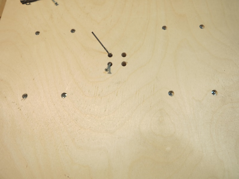
Figure 8. Fastening the running nut.
4 Assembling the machine portal.
For assembly you will need:
1) a set of milled parts for assembling a moving table
2) steel linear guides with a diameter of 16mm (2 pcs)
3) linear bearing LM16UU(4pcs)
4) lead screws for the Modelist 2030 milling machine - M12 (pitch 1.75mm) with ends processed at d=8mm and d=5mm.
For the Modelist 3030 milling machine - TR12x3 trapezoidal screws (3mm pitch) with ends processed at d=8mm.
5. radial bearings for fastening the lead screws - (2 pcs.)
6. running nut made of graphite-filled caprolon - (- 1 pc.)
4.1 Secure the side of the portal, Figure 9.

Figure 9. Assembly of the machine portal.
4.2 Insert the lead screw with nut into the Z-axis carriage frame, Figure 10.

Figure 10. Lead screw installation.
4.3 Insert linear guides, Figure 11.
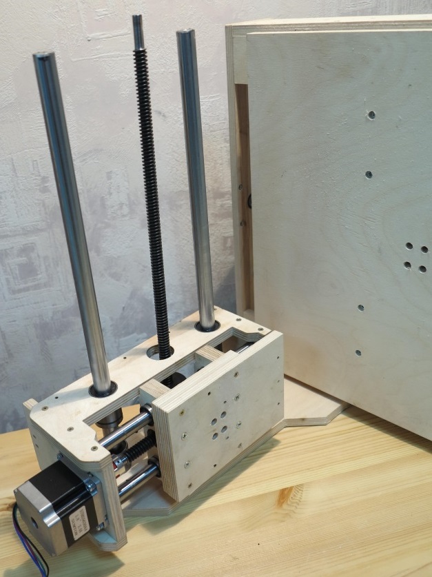
Figure 19 Fastening the lead screw “in space”.
4.4 Secure the second side of the portal, Figure 11.
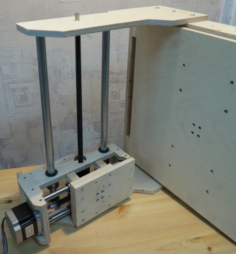
Figure 11. Installation of the second side of the portal
If the lead screw is not clamped by the parts of the base of the moving table and there is play along the axis, use a washer with a diameter of 8 mm.
4.5 Install and secure the rear wall of the Z carriage, Figure 12.

Figure 12. Fastening the rear wall of the Z carriage.
4.6 Secure the caprolon running nut with 3x20 screws from the kit, Figure 13.

Figure 13. X-Axis Running Nut Attachment.
4.7 Secure the rear wall of the portal, Figure 14, using 3x25 screws from the kit. 
Figure 14. Fastening the rear wall of the portal.
5 Installation of stepper motors.
To install stepper motors, use fastening parts from a set of CNC milled parts for assembling Nema23 stepper motor supports for the Modelist3030 milling machine.
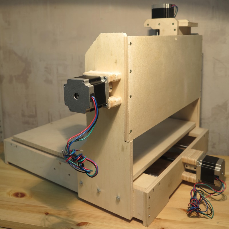
Figure 15. Installation of stepper motors.
Install 5x8mm couplings to connect the motor shaft to the lead screw. Attach the stepper motors to the machine; for fastening, use the M4x55 screw from the kit, Figure 15.
6 Attach the controller to the back wall of the milling and engraving machine, and connect the motor terminal blocks to it.
7 Installation of the router.
The router is fastened to the tool neck or body. The standard neck diameter of household routers is 43mm. Spindle diameter 300W - 52mm, fastening to the body. To install, assemble the router mount, the mounting details are in Figure 16. Use the 3x30mm screw from the kit.
Figure 16 43mm spindle mount
Figure 17 Spindle with mounting on a CNC machine
When installing Dremel-like tools (engravers), you will also need additional fastening engraver body to carriage Z with a clamp, Figure 18.

Figure 18 Mounting the engraver on milling machine.
It is possible to install a nozzle for connecting a vacuum cleaner
In order to perform a three-dimensional drawing on wooden surface, factory milling machines are usually used. But it is quite possible to make such a mini-model yourself, but first you need to familiarize yourself with the design. The basis may be a spare part from a printer, which can be purchased for pennies.
Operating principle of the machine
If you decide to make a CNC router with your own hands, you should familiarize yourself with the operating features of such equipment. It is designed to form a pattern on a wooden surface. The design must have electronic and mechanical parts. Together they allow you to automate your work.
To make a tabletop machine, you should know that the cutting element is a milling cutter. It is installed in a spindle on the shaft of an electric motor. The entire structure is fixed to the frame. It can move along two coordinate axes. To secure the workpiece, a support table should be made. An electronic control unit must be connected to stepper motors.
The motor and control unit ensure that the carriage moves relative to the part. This technology allows you to create three-dimensional drawings on the surface. Mini-equipment operates in a certain sequence. At the first stage, a program is written that will allow you to prepare a plan for moving the cutting part. For this purpose they are used software systems for adaptation in homemade models.
The next step is to install the workpiece. The program is entered into the CNC. The equipment turns on, and then automatic actions are monitored. In order to ensure maximum automation, it is necessary to draw up a diagram and select components.
Before you start making a CNC router with your own hands, you need to familiarize yourself with the factory models. To obtain complex patterns and designs, several types of cutters should be used. You can do some of them yourself, but for fine work you will need factory options.
Homemade machine diagram

The most difficult and important stage In the manufacture of the equipment described, the choice of circuit is important. It will depend on the degree of processing and the size of the workpiece. For everyday use, it is better to use a mini-machine that will be installed on a table. Suitable option is a design of two carriages that will move along the coordinate axes.
The bases can be polished metal rods. Carriages are installed on them. To create a transmission, you will need stepper motors and screws, which are complemented by rolling bearings. To automate the process, it is necessary to think through the electronic part. It will consist of:
- power supply;
- controller;
- drivers.
When making a CNC router with your own hands, you should familiarize yourself with design features devices. For example, a power supply is required to supply power to the stepper motors and controller chip. For this, a 12V 3A model is used. The controller is needed to send commands to the engine. To operate the device, a simple circuit for the controller will be sufficient, which will send commands to three motors.
The driver is also an element of regulation. He will be responsible for the moving part. For control, standard software systems should be used. One of them is KCam, which has a flexible structure to adapt to any controller. This complex has one important advantage, which is the ability to import files of common formats. Using the application, you can create a three-dimensional drawing of the workpiece for analysis.
In order for stepper motors to operate at a given input frequency, it will be necessary to enter into the control program technical specifications. When compiling a program, separate blocks should be made. They are intended for:
- drawing;
- milling;
- engravings;
- drilling.
This will eliminate idle movements of the cutter.
Selection of components

Before you make your own CNC router, you must select the components to assemble. A suitable option is to use improvised means. The basis of the machine can be plexiglass, aluminum or wood. For proper functioning of the complex, the design of the calipers must be developed. Their movement should not be accompanied by vibrations, which can cause inaccurate processing of the part.
Before assembly, components are checked for compatibility. As for the guides, they will be polished steel rods with a diameter of 12 mm. For the X axis the length is equivalent to 200 mm, for the Y axis - 90 mm. Before you start making a CNC router with your own hands, you must choose a support. A suitable option is textolite. The dimensions of the site will be as follows: 25x100x45 mm.
The cutter mounting block can be made from textolite. Its configuration will depend on the available tool. The power supply is usually used from the factory. If you want to do this work yourself, you must be prepared to possible errors which will negatively affect the operation of the equipment.
If you want to assemble a router with your own hands, then you can use the 24V model for this. As excellent option 5A also appears. It is quite often compared to disk drives, the first of which has more impressive power. To solder the controller board, you should use capacitors and resistors in SMD packages. This will reduce the parameters and make the interior space more optimized.
Instructions for making the machine

Once all the components have been selected, you can begin manufacturing the device. All elements are pre-checked, especially regarding their quality and parameters. Special parts should be used to secure the units. Their shape and configuration will depend on the chosen scheme.
The design must have a lift for the working tool. To do this, you should use a toothed belt. A mandatory element of equipment is the vertical axis. It can be made from an aluminum plate. This unit is adjusted to the dimensions that were obtained at the design stage and entered into the drawing.
Before making a CNC router with your own hands, you can cast a vertical axis using a muffle plate. Aluminum would be an excellent material. Two engines are mounted on the body, which will be located behind the axle. One of them will be responsible for horizontal movement, and the other for vertical movement. Rotation must be transmitted through belts. Once all the elements are in place, the machine must be set to manual control and its operation checked. If any shortcomings are identified, you can correct them on the spot.
More about stepper motors

CNC units must be equipped electric motors stepper type. As such a motor, you can use one that will be borrowed from a dot matrix printer. Usually they have quite powerful elements installed. Matrix units have steel rods based on durable material. They can also be used in a homemade machine.
If you are wondering how to make a CNC router with your own hands, it is recommended that you first consider the photo. They will allow you to understand how to proceed. The design may include three motors, which indicates the need to disassemble two dot matrix printers. It is better if the motors have five control wires, because the functionality of the machine will increase several times. When choosing a stepper motor, you should find out the number of degrees per step and the operating voltage. You should also know the winding resistance. This will allow you to configure the software correctly.
Shaft mounting
If you decide to make a CNC wood router with your own hands, then you can use a pin or nut of the appropriate size as a drive. It is better to fasten the shaft with a rubber cable with a thick winding. The same approach is also relevant when attaching the engine to a stud. You can make the clamps from a bushing with a screw. Nylon is used for this. The assistant tools in this case are a file and a drill.
Electronic support of the machine
The main element of the described equipment is software. You can use a homemade one, which will provide all the drivers for the controllers. The software must have power supplies and stepper motors. If you are faced with the task of how to assemble a CNC router with your own hands, you should take care of the presence of an LPT port. It will also be necessary working programm, providing control and management of the necessary operating modes.
The CNC unit itself is connected to the equipment through a port and installed motors. When choosing software for a machine it is necessary to rely on one that has already proven its stable work and has functionality. Electronics will affect the quality and accuracy of the operations performed. After installing it, you should download programs and drivers.
Do it yourself using the same technology. However, it can only handle thin workpieces. Before operating the device, it is necessary to check the operation of the electronic software and eliminate any shortcomings.
Instead of a conclusion: features of manufacturing a machine from drilling equipment
Before starting work on making a CNC router with your own hands, you need to review the instructions step by step. It may involve the use of one or another schematic diagram, on the basis of which the mini-equipment will operate. Sometimes it acts as such drilling machine, in which the working head is replaced with a milling one.
The most difficult thing is that you will have to design a mechanism that provides movement in 3 planes. This mechanism is usually assembled based on the same carriages from a non-working printer.
Software control is connected to the device. Using such a device it will be possible to work with workpieces made of sheet metal, wood or plastic. This is explained by the fact that the carriages from the old printer, which provide movement cutting tool, will not be able to guarantee a sufficient degree of rigidity.