Varieties of designs and technology for making sliding gates with your own hands. How to make sliding gates: step-by-step instructions with drawings Do-it-yourself sliding gates drawings diagrams
An integral part of the fencing structure summer cottage are the gates. Today there are many varieties of them. Let's look at the manufacturing and installation process sliding gates with your own hands.
Advantages and disadvantages of this design
Advantages:
- This gate design does not interfere with exit/entry vehicle in a small area. Cantilever doors can significantly save space.
- The presence of the lower fastening of the console system allows you to equip the gate in any climatic conditions.
- The finishing can be made from different materials, For example, vertical lathing, corrugated sheets, forging and more.
- Possibility to choose a design option, for example, from a sandwich panel or corrugated sheet.
- Compared to other types of gates (for example, swing gates), there is no such thing as sagging hinges. The existing automation and gate closing/opening mechanism provides for a long operational period.
- It is possible to choose different automation for gates.
Flaws:
- Unlike other types of gates, for example, swing gates, the installation of sliding gates requires more financial costs, approximately 10–20%.
- To attach the console part and the drive, it is necessary to make an additional foundation.
- You will need to allocate sufficient space along the fence.

The gate design is divided into several types, each of which differs from each other:
- Hanging. Since Soviet times, this has been difficult, but at the same time reliable design gained enormous popularity. In it, the canvas on roller trolleys is fixed to a beam, which is located above the passage, up to 5 m high. As a result, this height is a limitation when tall vehicles enter.
- Console. This type of gate is ideal for the climatic conditions of Russia. This design is not equipped with a beam above the driveway. Such gates will not be able to be damaged by snow drifts, wind, dust, etc. Thus, the canvas is fixed to the beam using roller carts. In this case, the entire structure is fixed on a powerful foundation, which is poured on the side of the opening.
- On screw piles. Metal piles are screwed into the ground to a depth of 1500 mm, which will support the entire structure. Their production and installation will take up to 3 days.
- Mechanical. These gates are opened/closed manually. Mechanical ones are much cheaper in cost and easier to install. They are suitable for those cases where a dacha or country house rarely used.
- Automatic. Such gates are the exact opposite of mechanical ones. They are equipped with an electric drive and remote control. The best option for regular use.
Regardless of the type of construction, sliding gates require free space along the fence on one side. In this case, it must be equal in size to the opening. As for console systems, the space should be 120–200% larger.
Gate calculation features

Design calculation is one of the most important and priority stages. You should not ignore this stage, since the construction of sliding ones is much more complicated than swing ones.
The calculation process includes the following steps:
- Determining the height and width of the opening. As a result, it will be possible to select the required type of gate for free movement.
- Estimation of the weight of the structure being constructed.
- Making a sketch or drawing.
The calculation of the width and height of the structure should be based on the market range. So, if a profile or pipe can be easily welded, then cutting sheets of corrugated board for the purpose of adding it is very difficult. Plus, the result will be unaesthetic.

Moreover, understanding the final weight of the structure, appropriate mechanisms and moving parts are selected that can cope with the load.
If the canvas is supposed to be large, then be sure to take into account wind load. Add a small margin to the existing wind force prevailing in your area.
Although the easiest option for obtaining calculations is to contact a specialized company that will provide a folder with drawings and calculations, you can do this yourself. It is worth immediately noting that all of the above calculations apply to cantilever-type sliding gates. They are more complex than all other types, so let’s look at them in more detail.

The gate width (L) will be equal to:
- opening width;
- technological opening/closing intervals;
- minimum distance between the centers of the carriages.
Based on this, L will be larger than the opening.

When moving, the doors must be balanced. This indicator is achieved by calculating the counterweight. Thanks to this, the specific gravity of the structure will be evenly distributed over the carriages. Accordingly, in order to have as little load as possible, the counterweight must be large.
But what if there is not enough space for the sash to move? In this case, it is necessary to understand that the length of the counterweight should not be less than 40% of the width of the sash. The ideal figure is 50%. As a consequence, the width L has a counterweight in its design.
Having such calculations, you can determine how much space is needed to roll back the gate along the fence.

This value is determined based on the weight of the material used:
- Corrugated sheeting ~ equal to 4 kg/m2.
- Steel, thickness 2 mm ~ 17 kg/m 2.
A gate with a 4x2 m frame will weigh on average 200 kg. Having such data, it is possible to determine the indicators of the guide beam. In this case, you can build on the established standard.
For a gate weighing 300 kg, a 9x5 cm beam with a thickness of at least 3.5 mm is sufficient. However, a safety margin of up to 40% is required. It will significantly simplify the operation of the gate and increase its service life.

The gate will require rollers, catchers and a support rail. Modern products such a plan allows you to choose necessary design. As a basis, we will take the simplest estimate of the wind load, which is equal to 12 m/s to 90 kg/m2 and is evenly distributed over the support zones of the canvas.
How to make sure that the structure you make, even with strong wind will it work without interruption? To do this, it is necessary to ensure that the strength of the fittings is greater than the calculated weight of the gate. A lateral moment of 100 kg/m is also taken into account, multiplied by 8 kg/m, which equals 800 kg/m. In principle, this is not much ~ 150–180 kg/m for each supporting element.
When buying a roller mechanism, make sure that it has a margin of up to 30% in relation to the weight of the gate. But this indicator does not affect the service life in any way. This is directly affected by increasing the distance between the centers of the carriages.

In addition to all of the above, it is worth paying attention to other aspects. Pay attention to the gate rail, supports for roller carriages and the number of anchors. It is also important to correctly calculate the mortgages on the support pillars. In this case, it is necessary to start from 60% of the total mass of the gate, divided by the number of mortgages.
As for the calculation of the foundation, then special secrets there is no. But despite this, you should not lose sight of this component, because often the cost of the foundation reaches 40% of the total cost of the project.

This type of gate has the following structural elements:
- Guide beam. Takes on all their weight.
- Trolley or roller support. You need 2 of them.
- Removable end roller. When closed, it serves as a support.
- Upper/lower catcher. When the gate is closed, the lower one takes the load, and the upper one reduces the windage.
- Bracket. It is important for keeping the sash from swinging sideways.
- Stand. A support is installed on it, which organizes the movement of the sash.
Roller supports are installed on the foundation, which take on the load of the guide beam. The rollers are placed inside the supporting console.
Sash selection

The gate leaves are also subject to high demands. Its design must be sufficiently rigid and stable. This is important so that the sash functions well in the event of a strong gust of wind or icy conditions. Moreover, it must be equipped with additional stiffening ribs so that it does not sag under its own weight. All this should be taken into account when creating drawings.

The availability of certain components directly depends on the height and width of the sash, as well as its weight. So, today on the market you can find a number of companies that provide quality equipment, namely:
- Combi Arialdo and Flatelli Comunello from Italy.
- Roltek and Doorhan from Russia.
- Alutech from Belarus.
For example, let's do some calculations. In the basic configuration, a supporting rail with a length of 6 m is necessarily installed. And in order to choose the right components for it, it is necessary to take into account the length of the sash plus 40%. Selection is also carried out according to the length of the guide beam and possible loads. So, if the width of the opening is 3.8 m, then the length of the door is 3.8 m + 40% = 5.32 m. In this case, you can purchase a ready-made set with a 6 m beam.
If the opening width significantly exceeds 4 m, then the purchase of components should be guided by a load of 500 kg. In them, the guide beam has a wall thickness of 3.5 m and a cross-section of 71 × 65 mm. If the width is more than 6 m, then it is necessary to take a load of up to 600 kg into account.
Installation work

The movement of the web should be carried out with inside area, namely along the fence. Based on this, it is necessary to prepare a place for the gate so that absolutely nothing interferes with this process.
The installation process includes 4 steps:
- Electrical wiring.
- Installation of a response pole.
- Automation installation.

Stages of foundation construction:
- First, marking is carried out. Measure 500 mm from the fence (the width of the foundation). You also measure from the edge of the gate a distance equal to the rollback (the length of the foundation). So, you will see the perimeter of the future foundation.
- It is often possible to use fence support posts. If this is not possible, then a counter post should be installed on the opposite side. It must be installed so that it is inside the area, and not in the opening itself. Otherwise, it will reduce the width of the opening.
- If the gate will operate automatically, then be sure to organize a place for laying the wiring. To do this, you can use a square metal or plastic pipe/box. The diameter of the pipes is not less than 25 mm.
- Now you can start digging a pit. The depth of the trench is up to 2 m, below the soil freezing level (different in each region).
- To make the embedded element, you can use channel 16. Its length should correspond to the length of the trench. Reinforcement Ø12 mm is laid in the foundation. The reinforcement must be welded to the channel and connected with cross braces.
- Thus, the resulting embedded element is placed with the reinforcement down. When laying, make sure that the side of the channel is adjacent to the fence support post. Also, the channel must be set strictly level and exactly parallel to the gate opening line.
The embedded element must be flush with road surface. The minimum gap allowed between the bottom edge of the gate and the road is 10 cm. This gap can be increased using an adjustment platform. But it will be impossible to reduce this gap without breaking the fastenings.

If for one reason or another a gap of 100 mm is not suitable, then install the embedded element deeply.
Concerning concrete works, then they are carried out when the installation of the embedded element is completely completed. The concrete level should be flush with the embedded element.
Installation

When the foundation has hardened, you can begin installing the gate. To do this, you first need to make markings. Along the line of the opening, not reaching the counter post 30 mm, pull the cord. This cord is the gate's movement path. The height of the cord tension is 200 mm. Further work as follows:
- Determine the extreme position of the first and second roller support. From the edge of the opening, step back 15 cm along the plane of the embedded element and draw a line for the position of the outermost first trolley. Calculate the line of the second cart as follows: measure the entire length of the gate with the cantilever part and subtract 10 cm from the edge of the return post along the plane of the embedded element. As a result, you will determine the location of the second cart.
- Now insert the roller supports into the supporting profile, placing them in the center.
Afterwards it is necessary to weld the second trolley of the adjustment platform. Then roll the gate leaf into the opening and make final position adjustments. Make small tack welds by welding the second adjustment pad, the resulting action looks like this:
- Remove the canvas from the roller cart.
- Next, remove the carts from the platforms.
- Weld the platforms to the embedded element.
- Attach roller carts to them.
- Slide the canvas onto the roller supports.
- Close the gate and wrench adjust their position.

Inside load-bearing profile make holes, this is necessary in order to install the cart correctly. To do this, loosen the top nuts securing the carts to the platforms. After that, roll the gate back and forth. If the sash moves freely, tighten the nuts. If there are some difficulties in moving the sash, then slightly loosen the fasteners and level out all the design flaws, for example, correct the distortions of the trolley.

- Now you need to install the end roller. It should be inserted into the supporting profile and the bolts should be tightened thoroughly. You also weld the end roller cover to the profile. This will allow the roller to act as an end stop in the case of manual gate operation. But in this case, fastening by welding will be much better than a bolt.
- As for the support profile plug, it is installed on the inside of the gate and welded in place. It is necessary to prevent snow from rolling under the rollers.
- Now the upper clamp is mounted to the rollers. Therefore, loosen the roller fasteners and install the brackets so that its side is directed towards the support post, and the rollers grip the top of the canvas. Taking this into account, press the bracket against the post and secure it.
On next stage work is carried out covering the gate frame. For this you can use profiled metal sheets. They must be cut to the size of the sash. Fastening is carried out with rivets or self-tapping screws. Each subsequent sheet is mounted with an overlap.

When the casing is completed, the lower/upper catcher can be installed. The lower catcher plays the role of reducing the load on the roller carts when closed. Therefore, they must be installed when the gate is loaded. Place the lower catcher under the end roller with the gate completely closed so that the supporting plane of the catcher is above the level of the end roller. As for installing the upper catcher, this process occurs in the same way.

Finally, all that remains is to install the automation. To do this, attach the gear rack, which means a universal part with an electric drive. It is usually included in the mounting kit.

The choice of automation directly depends on the weight of the gate:
- For an opening of 4 m, a drive of 500–600 kg is used.
- For an opening of 4–6 m, a drive is used – 600–1300 kg
- For cases with intensive gate opening, a drive of 1200–1800 kg is used.
Coloring

All metal elements of the gate must be painted. Pre-degrease the surface. To do this, clean the surface and sand it with a sanding disc on a grinder. Wipe some areas, such as protected areas, with acetone. Now you can start priming. It is applied evenly. Moreover, the primer must be applied so that there are no drops or streaks. Thanks to such preparatory work, the paint will lie evenly. As a result, the entire gate structure will be completely protected from corrosion.
The paint should be applied in two layers and only after the first has completely dried.

To carry out all the work, you will need to have the following tool:
- Inverter welding material. Such a unit will not damage the metal.
- Bulgarian.
- Air compressor for painting.
- Pliers.
- Drill.
- Roulette.
- Level.
- Riveter.

If you do not have sufficient experience in performing such work, then there is a high risk of making some mistakes:
- Insufficient foundation preparation.
- Incorrect installation and fastening of all components.
- Incorrect weight of the gate for the load-bearing beam.
- If you hear a creaking sound, this is evidence of sand getting into the bearings.
- Do not allow paint to drip.
- Be sure to take into account the depth of soil freezing. Otherwise, the pillars may skew in one direction.
Video: making gates
Photo: options for finished sliding gates


Scheme
In the diagrams you can find many structural details for the manufacture of sliding gates:


IN Lately, when every wealthy citizen wants to acquire his own private house or cottage, he is faced with the question of building a fence and, as a result, a gate suitable for it.
Sliding and sliding gates are very popular in this regard due to their obvious practicality; They are also often used in industrial facilities.

With the increase in demand, the number of manufacturers engaged in the production of both finished gates, as well as their components, offering installation by qualified workers.
Types of sliding gates
Gates are divided into several types, and each has its own design, which has its own pros and cons.

Hanging gates
Most often they are used at the entrances of industrial facilities and other areas intended for a not too wide range of people. This type of gate is very reliable, but its production requires a lot of materials and, as a result, finances.

However, for those who value quality above all, they will be to their taste: hanging gates can work even fifty years after installation.

Among the obvious disadvantages, in addition to the price, it is worth noting that the gate opening is quite limited due to the upper beam.
Sliding gates on rails
In theory, the most reliable and at the same time the most primitive gate design. The gate opens like a compartment door, sliding on rollers along a specialized rail that is located on the ground.

Despite all the ease of use, in the climate of our country problems may arise with this type of gate; weather conditions such as snow or falling leaves can block the movement of these gates by closing the rail, making them impossible to open and difficult to return to functionality.

This design will find greatest application in places where the area is subject to timely cleaning, for example, in private courtyards. Also, even when open, such gates do not take up extra space, which obviously gives them an advantage in places with limited space.

Console gates
The design of this type of gate is similar to sliding gates on a rail, but differs in that the gate has no contact with the ground rail. This is the most complex design However, this gives it its advantages: weather conditions do not affect the operation of the gate, and they also leave a lot of free space, negating the risk of damage to the vehicle entering them.

Thanks to the convenient arrangement of the rolling elements, which directly ensure the operation of the gate, cantilever gates are independent of nature, which allows them to have increased strength.
The gate movement is very simple thanks to the well-designed design and reduced friction. The disadvantages include the complex installation and the need for a larger fence area than the size of the opening.

When can sliding gates be installed?
To install the desired type of sliding gate, sometimes a great desire and budget are not enough; The success of the installation largely depends on the type of site on which the gate is going to be located.

In some situations, installing a gate is either completely impossible or very complicated.

For example, the problem with space is always very acute. With a short fence, you can’t even dream of a gate, since the space into which the gate will roll back must be unobstructed by at least the width of the opening, multiplied by one and a half.

The reason for this is that in addition to the gate itself, its technological part also takes up a lot of space.
Note!


In addition, the fence must be straight, since the gate moves in a straight path. Yes, a very obvious fact, but many consumers forget to take it into account. There should also be no uneven terrain where the gate opens.
How to install sliding gates
Installing and making gates with your own hands without experience in this matter can be very difficult, but possible. After reviewing the photographs of sliding gates, construction detailed plans and drawings and diagrams of sliding gates, you can begin installation.

First of all, you should evaluate the future location of the gate. Assess the condition of the support posts and make sure they are strong enough to install the gate.

Make sure it is possible to locate a hole near a foundation pillar with dimensions of 500x2000mm

Decide on the type of gate leaf and its facing material; this is important because the mass of the gate depends on this, and the choice of power elements depends on it.
Draw up detailed drawings of the gates, taking into account the characteristics of the area where the installation will be carried out, and purchase components.
Note!


Carry out marking work. Select the zero level.

Proceed with installation of the gate foundation. When using an electric drive in the selected type of gate, at this stage you should pay attention in advance to laying the necessary cables.

Make a sliding gate leaf. It is very important to pay great attention to the sizes. Buy necessary fittings for sliding gates (roller supports, rollers, beam caps, etc.)

Carry out installation and installation of the structure, having first waited no less than seven days after the completion of concreting.

DIY sliding gate photo

Note!


Sliding gates, or sliding gates as they are also called, are very convenient, save space, and when connected to automation, they also become comfortable - you don’t have to get out of the car to open them. Let's look at the design of sliding gates that you can make with your own hands.
We will consider the advantages various designs sliding gates, criteria for choosing fittings and drives. We will show you the stages of manufacturing and installation. The examples are accompanied by comparative tables, drawings and diagrams.
Advantages of sliding gates
The main advantages of sliding gates are:
- saving site area;
- structural rigidity, high resistance to wind loads;
- durability and long-term operation;
- the ability to cover a wide opening;
- ease of control and comfort (for automatic models);
- modern, status look.
Disadvantages include the relatively high cost of components and dependence on electricity to power the drive.
Types of structures
Structurally, sliding gates are divided into cantilever gates (the gate leaf moves along the top guide) and monorail gates (the gate slides along a rail located above the ground level).
- mild climate without significant winter precipitation;
- the need to pass oversized vehicles or special equipment that may be interfered with by the console.

When driving through such a gate, you will have to put up with the obstacle of crossing a rail located just above the “0” mark.
Cantilever gates are better protected from precipitation, and for regions with snowy winters, their design is preferable.
The gate leaf can be moved manually or automatically. The question of choosing from these options is the price and the comfort requirements of the vehicle owner. Additional convenience is provided by the installation of a wicket door equipped with its own locking device. The gates also differ in the way they are covered:
- corrugated sheeting (one- and two-sided sheathing);
- rolled product - sheet or rod;
- forged metal;
- lumber.

Before choosing a covering, you should take into account that the materials have different weights. The greater the weight of the cladding, the more metal-intensive the sash frame must be, the higher the drive power, the more expensive the fittings and motor. The easiest way is to cover it with corrugated sheets, especially one-sided. The weight of a steel sheet depends on its thickness, but it is not recommended to use rolled products that are too thin. Wood paneling can be quite massive due to the thickness of the material. Structures made from welded rods or openwork forged ones may not be too heavy, but in this case the area remains in full view of passers-by, which not everyone likes. Forged canvas with a backing is the heaviest. Moving such a mass may require industrial fittings and a drive.
Selection of accessories
Complete set of purchased accessories
The fittings are selected according to the weight of the gate and the width of the passage. It is desirable that the fittings kit consist of the following elements:
- load-bearing beam(guide profile);
- roller carriages (roller support);
- end roller;
- upper support rollers;
- upper and lower catchers;
- stubs.
 Components of sliding gates: 1 - electric drive; 2 — roller bearings; 3 — adjustable stands; 4 - guide; 5 - end roller; 6 — lower catcher; 7 — toothed rack; 8 — upper roller catcher; 9 - supporting rollers
The length of the supporting beam should be 1.35-1.5 times the width of the passage (a smaller figure is acceptable for the lightest gates). In this element, the precise geometry of the profile and the absence of curvature along the length are important to prevent the rollers from jamming. The gate moves on roller carriages. Rollers can be made of plastic or steel. In this unit, you need to pay attention to the bearings used - the reliability of the design depends on them.
The end roller is designed to partially relieve the roller bearings. The upper rollers support the door leaf. Their frame must be made of steel with a thickness of at least 3 mm. Experts recommend choosing rubber rollers as they are more gentle on frame paint. In the case of plastic rollers, it is recommended to install an aluminum pad under them. The lower and upper catchers fix the gate in the closed position. A kit without a top catcher for high gates is not very convenient. The plugs protect the guide from moisture and dirt.
Comparison of sliding gate fittings from different manufacturers
The market offers accessories of various price categories from domestic and imported manufacturers. To get your bearings, let’s consider some options, and for a correct comparison, we took fittings with approximately the same gate weight - from 400 to 500 kg.
Comparative table of offers for fittings from various manufacturers
| Manufacturer | A country | Gate weight | Cost as of February 2016 | Completeness data |
| Rolling Center | Italy | 500 kg | 13,500 rub. | Carrier trolley - 2 pcs, carrier beam - 6m, end roller - 1 set, end roller catcher - 1 set, support rollers - 1 set. |
| Alutech | Belarus | 500 kg | 10,800 rub. | Roller support - 2 pcs., guide bar - 6 m, plug for the guide bar, end roller, lower catcher, upper bracket with 2 rubber rollers. |
| Welser Profile | Austria | 500 kg | 12,000 rub. | Roller carriages - 2 pcs., guide - 6 m, upper and lower catcher, support roller, end roller, guide plugs - 2 pcs. |
| Doorhan | Russia | 400 kg | 12,700 rub. | The kit includes: cantilever pipe - 6 m, pipe plug - 1 pc., trolley with rollers - 2 pcs., end roller catcher - 1 pc., end roller - 1 pc., guide bracket with rollers - 1 pc. |
| Deva | Ukraine | 400 kg | 7,500 rub. | The fittings are made in China, the guide profile is made in Russia. Knurling roller without metal plug, roller made of strong polymer. |
| "Roltek" | Russia | 500 kg | 12,700 rub. | Guide rail 6 m - 1 pc., roller support - 2 pcs., upper bracket with rollers - 1 pc., removable end roller - 1 pc., end roller catcher - 1 pc., upper roller catcher - 1 pc., plug - 1 PC. |
| Svit-Vorit | Ukraine | 400 kg | 8,500 rub. | Guide - 6 m, roller carriage up to 400 kg - 2 pcs., upper support rollers, knurling roller with a polymer wheel, lower and upper catcher, rubber plugs, no bearing inside the wheel. |
| Came | Italy | 500 kg | RUB 13,700 | Trolley S with 8 rollers - 2 pcs., end roller, concentration catcher. roller, rail plug - 2 pcs., FRS 2 guide bracket with 2 rollers, M10x25 screws - 15 pcs. Guide rail S non-galvanized. |
| Fratelli Comunello | Italy | 500 kg | 15,000 rub. | The recommended opening width should not exceed 4.5 meters, the height should not exceed 2.5 meters. Beam dimensions (w-h-d): 65x65x6000 mm, wall thickness: 3.5 mm. |
| Combi Arialdo | Italy | 450 kg | 16,800 rub. | Guide rail 6 m - 1 pc., roller support 2 pcs., upper bracket with rollers 1 pc., removable end roller 1 pc., end roller catcher 1 pc. |
Drive selection
If you decide to install automatic gates, you can buy a ready-made kit consisting of a motor and a remote control, or you can make it yourself. For the drive to operate, one more element is required - a gear rack, which, as a rule, is not included in the hardware kit.
Gate automation
Since there are a large number of offers from various manufacturers with different characteristics, we have collected the most popular of them in a comparison table for a gate weight of 400-500 kg. When comparing, pay attention to the drive power and intensity of use - these are the most significant criteria.
Comparison table for drives from different manufacturers
| Manufacturer | A country | Gate weight | Cost as of February 2016 | Completeness data |
| Doorhan | Russia | 800 kg* | RUB 17,475 | Sliding-800 KIT. Oil bath drive kit, 230 V, intensity 50%. Opening speed 12 m/min. Set: drive with built-in control unit, 4 m rack, signal lamp with built-in antenna, safety photocells, key switch, remote control. |
| Came | Italy | 500 kg | RUB 28,125 | Came BX-78 KIT. Main characteristics: 230 V, self-locking, for gates with a motion control and obstacle detection sensor (encoder), intensity 30%. Set: electric drive, built-in control unit, 4 m rack with mounting kit, AF43s radio, Kiaro 230N warning lamp, safety photocells, 2 control panels. |
| Faac | Italy | 500 kg | RUB 13,125 | 230 V, intensity 30%. Opening speed 12 m/min. Set: Drive 740 E, control unit 740 D, 230 V, Z16, V 12 m/min, magnetic limit switches, grease, with mounting plate. |
| Nice | Italy | 500 kg | RUB 15,825 | Ro 500 KCE. Intensity 9 cycles/hour, speed 0.18 m/s, adjustable speed, force, pause, acceleration and deceleration at end points, obstacle detection, gate function. Set: electric drive, built-in control unit, radio receiver, 2 remote controls. |
| Sommer | Germany | 400 kg | 16,400 rub. | Gator SG1. For gates 6 m. Maximum drive speed 200 mm/s, maximum traction force 800 N, max. power consumption 51 W, motor supply voltage 24 V. Includes 5 m of plastic coated rack. Built-in receiver and 1 4-button remote control. Obstacle detection function. Extended operating temperature range. Unlocking with a key. |
| BFT | Italy | 500 | RUB 11,840 | BFT DEIMOS BT. Motor power supply 24 V, power 50 W, speed 13 m/min, intensity of use - intensive, torque 10 Nm. Set: Deimos BT drive + built-in A600 control unit + built-in 2-channel radio receiver Clonix-2 for 63 users. Self-locking electric drive. Electronic adjustable torque limiter. Built-in 2-channel radio receiver. 2nd radio channel - gate mode only. A rack is required for installation. |
| Somfy International | France | 500 kg | 18,800 rub. | Somfy ELIXO 500 230 V RTS. Set: Elixo 500 230 V RTS drive - 1 pc. Keygo RTS radio remote control 4-channel - 2 pcs. External RTS antenna with 8 m cable - 1 pc. Power supply type - 230 V DC. current. Power consumption - 290 W, capacitor - 1 mF, gear ratio - 1/30, travel speed - 8.5 m/min, obstacle detection - mechanical, maximum amount cycles per day - 100, control unit - built-in with microswitches, maximum number of radio transmitters - 36. |
| FAAC | Italy | 500 kg | RUB 10,320 | FAAC 740 drive with built-in control board and mounting plate (art. 109780) - 1 set. Power supply voltage 230 V, 50 (60) Hz, power consumption 350 W, current consumption 1.5 A, traction and pushing force 45 daN, engine rotation speed 1400 rpm, engine thermal protection temperature 140 °C, gear ratio 1: 25, gate speed 12 m/min (star Z16). |
* For gates weighing 300 kg the price is slightly lower
DIY gate drive
If desired, you can make the drive yourself. We talked about this in detail in the article"Do-it-yourself sliding gate drive".
Also watch two videos with different solutions.
Video No. 1: Drive for sliding gates based on a screwdriver
The system is controlled by 6 relays: switching from 12 to 220 V, providing 220 V to the screwdriver, and 12 V to the car alarm.
Video No. 2: Drive based on purchased and used elements
For safe work automation, it is advisable to install a signal lamp and photocells.
 Typical gate automation connection diagram
We talked in detail about automatic sliding gates in the articles:
- “Automation for sliding gates. Electrical circuit assembly"
- “Automation for swing gates. Remote control"
Gate leaf manufacturing and installation stages
Before starting work, decide on the dimensions of the gate - width and height. In our example, we consider an option with a passage width of 4 m, a guide length of 6 m, and a gate height of 2 m.
Materials and tools
The calculation of materials was made for the structure shown in the drawing, with one-sided sheathing with corrugated sheets, for a climate where the soil freezes to a depth of 1.5 m.
 Gate drawing
Table. Material consumption for installing sliding gates
| Material | Consumption | |
| Concreting the load frame to a depth of 1.5 m | cement | 150 kg |
| sand | 450 kg | |
| crushed stone | 450 kg | |
| fittings, diameter 10-14 mm | ~20 m | |
| Mortgage | channel No. 16 - No. 20 | 2 m |
| Nashchelnik | square pipe 60x60x2 mm | 2.5 m |
| Gate leaf (4x2 m) | corrugated sheet | 10 m 2 |
| rectangular pipe 60x40x2 mm | 26 m | |
| rectangular pipe 40x20x2 mm | 20 m | |
| dye | 1 jar | |
| primer | 1 jar | |
| solvent | 1 jar | |
| electrodes | 1 package | |
| screws for metal | 150-200 pcs. |
Required tools:
- shovel;
- Bulgarian;
- welding machine;
- screwdriver;
- level;
- roulette;
- paint brush or spray bottle.
Making the sash
The frame frame is a welded structure. Before starting work, you need to organize the place - lay it out using building level bricks under future design. Make frame blanks. Clean the pipes from dirt and rust.
You will need pieces of pipe 60x40 mm long: 6 m - 1 piece, 4.4 m - 1 piece, 2 m - 2 pieces, 2.56 m - 1 piece.
And pipe sections 40x20 mm long: 4.32 m - 3 pcs., 1.92 m - 2 pcs., 1.88 m - 4 pcs.
To the guide (you need to buy), closed on both sides with plugs, weld a 60x40 mm pipe 6 m long, grabbing it on both sides every 750 mm. Perpendicular to the base, weld (also spot-weld) 60x40 mm pipes 2 m long (cutting the edges at 45°) and connect their tops with a 4.4 m long pipe.

From the free end of the base to the nearest corner, weld a 60x40 mm pipe 2.56 m long. Fill the area of the canvas with a structure of 40x20 mm pipes according to the diagram. In this case, the narrow pipe must be welded flush with the wide one - with one-sided sheathing and in the center - with double-sided sheathing.

Clean the weld seams with a grinder and treat with an anti-corrosion agent. Paint the resulting frame.
Cut the corrugated sheet and cover the frame using self-tapping screws.
Concrete works
Prepare the power frame. To do this, a structure 2.2 m long and 1.5 m high needs to be welded from reinforcement and channel according to the presented diagram.
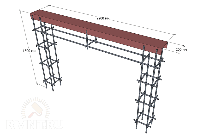 Frame diagram for concreting a power frame
Prepare a U-shaped pit for the frame as shown in the figure, prepare a solution based on the calculation of the material (in portions), install the frame and concrete the structure. Hardening time is at least a week.
 Load frame installation diagram
On the opposite side of the driveway, next to the fence post, install a post for attaching the upper rollers and catchers (catch plate). It can be concreted, or it can be welded to embedded structures from the corner, built into the fence post.

Installation of the structure
When purchasing accessories, you will be given installation instructions, but sometimes the seller simply does not have them. Let's consider the general case.
1. Weld the adjustable stand to the load frame (at the beginning and end, leaving the necessary clearance) and install the roller supports on the stand bolts.
2. Weld a platform for the drive to the load frame.
3. Install the gate on roller supports by threading the rollers into the slot in the guide beam. Using a level, level the adjustable stand. If a stand is not provided, the roller supports are welded to the embed (channel) after checking the horizontal position.

4. Weld the frame of the upper rollers to the mortgages on the post on the side of the load frame. Check that the door leaf is perfectly level.

5. Weld first the lower and then the upper catcher to the strip. The bottom catcher should be a few millimeters above the end roller of the guide. The top catcher is welded just below the top of the gate.

6. Bolt the end roller into the guide beam.
7. Install and connect the drive and, if necessary, the remote control.

Your gate is ready for use.
In the recent past, not everyone could afford to install sliding gates; the fittings were too expensive. And the automation installed on them was an absolute dream.
Now the situation has changed, a lot of high-quality and affordable fittings have appeared on the market, and many people prefer to make just such gates for themselves because of the simplicity of the design and saving space.
They can be built by anyone familiar with the basics of construction.
Types of sliding gates
Sliding gates are a functional, reliable locking mechanism that practically fits into the surrounding space.
The gate moves along the fence, using a minimum area, which can be calculated using the following formula: the width of the gate, taking into account the movement mechanism, is multiplied by the length of the moving sector.
There are three types of construction:
- . The supporting guide is placed on the lower leaf, moving, the gate does not come into contact with the ground and moves freely on top. This is the most common design;
- Hanging type. Suspended on roller trolleys, the gates are installed with a guide located above the opening. The entry/exit area is limited at the top. Such structures are placed in warehouse and production hangars, which have a limit in the upper space;
- Gates on wheels. The supporting rail is installed in the opening and the wheels are mounted to the gate itself. Moreover, it is located in the gate opening, on the foundation.

Cantilever gates
The most successful are sliding gates with a cantilever-type design. The space at the top is free, unlike the suspended type design. The same maintenance (cleaning from ice, snow, leaves) is not required as with a structure on wheels.
Advantages and disadvantages
The advantages of such gates are:
- possibility of passage of any transport (height is not limited in any way);
- the opening process occurs along the fence line on which the gate is installed, which significantly saves space on the site;
- in order to open them, you need to use a minimum of effort, unlike swing ones;
- good burglary resistance (can withstand the ramming of a powerful truck);
- less influence of windage;
- the required automation costs significantly less than swing automation;
- the prestige of owning such a gate.
- price, which includes expensive branded equipment and a special foundation;
- heavy and cumbersome design (the length of the gate should be 30-50% greater than the length of the opening, and the weight of swing gates should be two to three times greater);
- Availability free space along the fence (usually 5-8 meters).
Accessories used for installation
Thanks to the fittings, the gates are stable and moveable. The success and reliability of the installation depends on their correct choice. You can buy ready-made kits on the construction market.
When choosing, you must be guided by the following rules:
- the sash should be 40% wider than the opening;
- The fitting kit is selected taking into account the length of the guide beam, as well as the upcoming load and the intended installation of the automation.
So, for openings no more than 4 meters, a set of components is purchased for the required load, not exceeding 500 kg.
This kit includes a guide beam with a cross section of 71x65 mm, a length of 6 m and a wall thickness of 3.5 mm. And for openings of no more than 5 meters, components are purchased that can withstand a load of a maximum of 600 kg.

You can also purchase the hardware kit separately. This:
- Roller carriages, with the help of which the gate rolls freely along the base.
- Guide rail or a guide, which is welded to the frame from below and, together with the canvas, is put on the roller carriages. This is the base that holds the carriages and the door leaf together and rolls them on rollers.
- Support rollers. Mounted on top of the post of the opening located nearby. They hold the sliding gate structure in a vertical position.
- Knurling roller and catcher. The roller is mounted in the guide, and the catcher is mounted on the nearest post of the gate opening. When the gate is closed, the rolling roller gradually moves into the catcher.
- Stubs. This is a protective material that prevents rain, dirt, snow, and sand from penetrating the guide rail.
Drawings and diagrams for installation
As a rule, construction begins with drawing up drawings. Below are several diagrams and drawings of sliding gates that are recommended for DIY installation. The choice of what you need is yours.
Also, by combining everything you need and cutting off the unnecessary, you can create your own drawing for your dacha or home. When choosing a material, you need to be guided by its compatibility with existing buildings.
This is the most simple circuit without electric motor and drive:

The drawing shows an automatic metal sliding gate:

The section must be 6 m with an entrance width of 4 m. In this case, a minimum road clearance of 75 mm is required, and the base must be mounted on concrete pillars, i.e. into a foundation dug 1.5 m deep. To prevent the gate from sagging under its own weight, the main section is reinforced by fixing it with special catchers.
Below is another diagram of a prefabricated structure with a section, support pillars and a foundation for the base.

Drawing with an electric drive that automates sectional movement. Diagram of the structure being built, taking into account the further installation of the auto drive. Installation will, of course, be expensive, but it will pay off by making it easier to open and close the gates and control them.

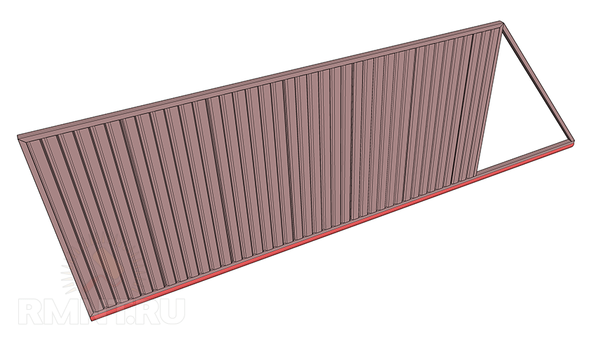
A movable metal section, equipped with a counterweight and ready for installation. All that remains is to sheathe it.

Such a section must be made not heavy, to facilitate its opening/closing. Also lightweight, it will not sag or deform. This will save you from completely unnecessary breakdowns.
And when further installing an automatic drive, such a section will require a less powerful motor, which will save money. Shown below is a sliding gate section made from polycarbonate, known for its excellent lightweight properties.

And the last diagram shows correct parameters and sliding gate ratio. All this is in the upper diagrams, but repeated helpful information not prevent.

Self-production
After all of the above, you can proceed directly to installing the structure.
The first step is to make the foundation and guides. To do this, two or three pillars 1.5 m high are driven into the ground. The value may vary and depends on the parameters of the gate being built.
Holes are dug, covered with a drainage layer and reinforced. Then the pillars and the foundation between them are filled with mortar. The main block will stand here, which will secure the movable section (and maybe the section drive).

After this, the gate posts are installed. They can be made of brick, concrete, welded pipes. When installing, you should take into account that the distance between them will be used for further installation of the gate.
The drawing below shows all the fasteners that will need to be installed on the posts and base to secure the movable section.

1. Guide beam; 2. Roller supports or trolleys; 3. Removable end roller; 4. Lower catcher; 5. Upper catcher; 6. Upper clamp with rollers; 7. Plate for fixing roller supports
It is necessary to install a channel on the made foundation of the base, and then on the pillars or wall (depending on the design) a trolley and fixing brackets with rollers. The gate section will move along them in the future.

On the other side of the structure we mount a section catcher and an end roller.
The sequence of work and components may vary depending on the chosen scheme!
Sliding gates require a metal section that opens and closes the entrance/exit to the site. It and the frame are welded exactly to size; the correct operation of the device depends on this. An example and section diagram is shown above.
The manufactured section must be sheathed suitable materials. They should be light, practical, and functional. Sheets of metal, stainless steel, corrugated sheets, and polycarbonate are suitable. The choice is up to the builder.
After this, the structure is sheathed with rivets, bolts, and screws.
Finally, the moving part is mounted on the prepared structure. The fixing brackets are removed and the section is secured to the channel (guide rail). Then the fixing brackets are placed in their original place. The work, in general, is not difficult, it only requires accuracy and precision.

After studying the diagrams and recommendations for installing sliding gates, you need to decide own projects and algorithms for mounting this structure, corresponding to the parameters and requirements necessary for a particular site.
You can see how to make sliding gates with your own hands from corrugated sheets in the video clip:
Another option:
Most builders who build a sliding gate structure on their own site with their own hands install roller carriages on platforms with welded studs.

“This is, of course, convenient and practical. After all, replacement in the event of a breakdown will be carried out easily and quickly!”: they think. But this is a mistake.
If the installation is done incorrectly, the channel will need to be drilled again, threaded, installed required size and so on.
The tiny distance will require several days of repair work and will end with cutting out the stud and welding the carriage to the base of the foundation.
Therefore, you need to follow proven instructions, this will allow you to install this design V minimum terms, saving effort and money.
Yes, sliding gates will not be cheap, but with the simplicity and manufacturability of the device, they will give a head start to swing and overhead gates. Installed strictly according to the right technologies, they are less likely to deform and jam.
There is a lot of incomplete information on the Internet about installing sliding gates with your own hands; after reading it, the progress of the work or the design of the sliding gate itself is not particularly clear.
In this manual, we will try to clearly demonstrate the installation of cantilever sliding gates inside and out, and help you calculate the height and width of the gate specifically for you.
To begin installation, you need drawings; there is no one drawing for all gates; it all depends on the width and height of the opening in the fence.
Accessories for sliding gates
The first thing you can start assembling the gate with is the fittings, but only after calculating the weight and dimensions of the gate, the fittings can be purchased separately or made with your own hands from bearings, the fitting kit includes:
- the guide rail is usually 6 m long;
- 2 roller bearings
- 1 top roller bracket to prevent the gate from swinging;
- 1 end roller;
- 1 end roller catcher so that during windy conditions the gate is docked correctly and does not break the automation.


Additional accessories for fittings:
- Mounting and adjusting support for roller bearings.
- Mechanical lock.
- The rack is toothed.
- Fastening element for toothed rack.
Now about the load. There are different sets for different gate weights, see the table, it shows the relationship between the weight and width of the gate.
| Opening width no more | Gate weight |
| 4 m. | 300 kg. |
| 4 m. | 400 kg. |
| 4.5 m. | 500 kg. |
| 6 m. | 600 kg. |
| 10 m. | 1000 kg. |
| 12 m. | 1200 kg. |
This data will be useful to you when choosing accessories, but most craftsmen try to make all the parts with their own hands, since the kit is not cheap.
To make the fittings yourself, you need to know where and why they are attached, read about this below.
How to choose quality fittings
The main part, the rail guide, best choice there will be rails from a European manufacturer. Detail good quality has a mirror-smooth surface and clear geometric shapes. The part must be galvanized and have no scale or rust on its surface. A high-quality guide has a metal thickness from 3.5 mm to 5 mm.
When choosing roller bearings, pay attention that they are made entirely of metal; plastic or rubberized ones will not last long. All geometric shapes of the metal must be correct; the slightest deviation indicates poor quality assembly.
As for the remaining metal parts, they must be coated with zinc, the shade of zinc must be uniform, minimum thickness metal 3-4 mm.
Sliding gate sizes
The cost of the fittings will depend on the size and weight of the sliding gate. The width is calculated in this way; another 50% of the width is added to the width of the opening in the fence. For example, your opening width is 4 meters, divide by 2, we get 2 meters + 4 meters opening width, the total length of the guide rail will be 6 meters.
To make it easier to understand and remember, I propose a formula and diagram:
- B - opening width;
- A - counterweight length;
- L is the length of the guide rail.

Once you have decided on the size of the frame, you can begin to manufacture it; the frame is made from a profile metal pipe 40x40x 2 mm and 40x20x2 mm for internal lathing. For aluminum frames, a profile of 60 mm or more is used.
It is better to make the height of the gate frame equal to the length of the corrugated sheet. It is better to choose tougher corrugated sheeting. Before attaching the corrugated sheeting to the frame, drill holes in the frame that are half smaller than the diameter of the roofing screw, since the self-tapping screw may not drill through the profiled pipe of the frame; blind rivets can be used instead of self-tapping screws.
The width of the lower profiled pipe must correspond to the width of the guide rail.
If your gate width is more than 4 meters, then it is better to use rectangular pipes to assemble the frame base!


The photo below shows how to properly make a frame for different opening widths.


Gate foundation
It is quite easy to determine the size of the foundation, since it has a length equal to 1/2 the width of the opening, according to the formula:
- B - opening width;
- L - foundation length;

If everything is simple with the length of the foundation, then with installation we have many options.
The foundation can be made of the following materials:
- Monolithic U-shaped.
- Solid monolithic.
- From screw piles.
In editing monolithic foundation There are also small features; you can use reinforcement welded to the channel, anchor bolts or long threaded studs.


Let's consider the option with a channel (power frame), it can be with one or two support pillars or without them, in both cases the power frame is attached flush to existing poles fence The height of the support pillars corresponds to the height of the gate itself + the height of the roller supports. Using two support posts near the load frame is advisable for wide gates that sway strongly in the wind. If support pillars are not provided, then instead of them, metal mortgages are made into the stone fence.


In the photo, laying the foundation.


Scheme without metal racks.


Location of carrier rollers


In order to level the power frame on the opposite side, where the support post with the end roller catcher is located, step back 10 cm (the thickness of the post) from the fence and pull the cord to the last corner of the channel; along its entire length, the edge of the channel should follow the line of the cord.
Gate installation and adjustment
After the load frame is ready for use, align the roller supports and install the upper roller bracket; installation depends on the design of the bracket.


To determine in advance where to mount the lower trap, a guide rail without a gate is placed on the roller supports. The lower trap is designed not only to hold the gate horizontally, but also to remove the load from the roller supports; for this, the end roller must be rolled into the trap so that the gate is raised up by 3-5 mm.


If, after installing the frame, the end roller is too sagging, adjust the roller supports.
If everything was done correctly, but you did not achieve proper operation sliding gates, then most likely you have a low-quality set of fittings, it is designed for a different weight, or the frame is assembled incorrectly, because of this the gate sag a lot and cannot fall into the lower trap.
After all the mechanisms described above have been adjusted, you can begin installing the automation. The video below shows how you can make an electric drive with your own hands.


Let's start with the rack, they come in metal and nylon, metal is naturally better and more reliable. Their thickness varies from 8 to 30 mm. Standard size slats 1 meter. For fastening, use a number of rails equal to the width of the opening + 1 rail for automatic limit switches. The gap between the teeth of the drive gear and the rack should be 1-2 mm. The rack is attached to the lower pipe of the gate frame using a fastening element for the rack. The holes in the rail allow you to adjust its height.

The picture shows two options for fastening the gear rack; we do not recommend attaching the rack to the guide rail; during welding, the guide may bend if bolts are screwed into the guide; this can also cause difficulties during installation and during operation of the gate.
Often the fasteners are welded, although for their fastening there is a special C-profile for the rack. The photo below shows both options.


If you buy an electric drive, it will come with 4 meters of gear rack.
For those who do not want to spend money on a rack, it can be replaced bicycle chain or as shown in one of the videos on a chain from a Lada car.
Gate automation
Both sliding and swing doors can open automatically. Their operation is controlled using a remote control and switches installed in the house, and possibly at the gate. One remote control can operate not only gates, but also garage doors and even lights. Automatic drives consist of an electric motor, a moving rack and a control device. They can be purchased as a separate device, although it is better to order them together with the gate. Then you will be sure that the drive was selected correctly and there will be no surprises during assembly.
Sliding gates require one motor to move a rack attached to the bottom edge of the gate. And for sliding gates, two cylinders are required, one is attached to each of the leaves. The drive has a mechanism that allows you to open the gate in the event of a power failure. Modern drives can be powered by a battery charged from the mains or solar battery. The gates open automatically and require the installation of devices that ensure the safety of their use. Photocells are needed, thanks to which the doors do not move when an obstacle appears in their path. A signal lamp installed in a visible place will indicate that the gate is opening or closing.
Selecting an electric drive
When choosing a drive, it is important that the gears of the gearbox are made of steel or brass, but not plastic or silumin. Second important element, this is a limit switch, it controls the points to which the gate can open and close, the limit switch can be mechanical and reed switch (magnetic), as practice has shown, a mechanical one can freeze in winter time. As a rule, the quality of drive parts depends on its power; the higher the power of the drive, the better its assembly. As for the carrying capacity, it is indicated in the documentation.
Basic drive configuration:
- 4 meters of rack;
- photocells;
- warning lamp;
- remote control and receiver;
- mounting plate.
For those who do not know what photocells are needed for, they are 2 sensors that are mounted on the edges of the gate. When an obstacle appears between the photocells, the gate opens or closes, depending on how you program the automation.
Automation installation


First of all, the mounting plate for installing the drive is welded or screwed; it is supplied complete with the drive; with its help, you can adjust the height and angle of the drive.


After installing the drive, install magnetic sensors, photocells and signal lamp. As a rule, the drives are connected to the 220 network and, after software configuration, are immediately ready for operation.