Device for connecting wires. Reliable ways to connect electrical wires
It would seem that what could be simpler than connecting wires? After all, there are several ways to connect wires. This includes twisting wires, soldering wires, welding wires, crimping and connecting wires using a terminal block. Even a schoolchild knows the easiest way to twist conductors. You need to put the ends of the metal wires, called strands, together and twist them into one “pigtail”, and then wrap them with electrical tape. There is no need for a soldering iron, terminal block, connecting caps and other “unnecessaries”.
Any “own electrician” has mastered this operation. And, when the need arises, he applies this method in his daily practice. For example, it splices the power cord wires of a household appliance, tablet or computer adapter after a break.
Russian “technicians” use this technology for fastening wires everywhere. It’s just that the rules for constructing electrical installations of PES do not provide for “twisting”, all kinds of “bends” and “rivets”. There are no such electrical installation methods in other regulatory documents. Why?
We often don’t think about the consequences of such a “simplification”. Meanwhile, an unreliable contact will fail at the most inopportune moment; the power supply to consumers/power receivers can always be cut off. Voltage “surges” cause breakdown of the elements of the power cascades of complex SBT household appliances. Even special protection devices used in the most “sophisticated” models of foreign manufacturers cannot save you from breakdown.

The induction of short electromagnetic pulses with a voltage of several thousand volts onto the electronic filling causes “harmless” sparking at the joints. At the same time, the standard protection equipment that apartments are now equipped with (RCD, circuit breakers, fuses) such short low-current pulses are not “seen”, so they simply do not trigger, and we do not customarily install special devices for this. Uninterruptible power supplies for computers also did not become a panacea for surges transient processes. The occurrence of “poke” causes malfunctions in the operation of electronic equipment and computer equipment, leading to failure of electrical components and expensive functional modules.
Overheating at the site of a poor connection leads to even more catastrophic consequences; when current passes, the weakened connecting node becomes red-hot. This often causes fires and fires, causing enormous damage to the owners of the premises. Statistics show that 90% of all electrical wiring faults occur due to twists and poor contact connections of conductors. In turn, the very malfunction of electrical wiring and equipment, according to the Ministry of Emergency Situations, is the cause of one third of the fires that occur in Russia.

However, it so happened historically that several decades ago, in conditions of a shortage of electrical accessories/copper conductors, twisting aluminum wires was considered the main method used in electrical installation work Oh. Twisting as a connection can be used in electrical engineering when carrying out repair and restoration work.

How to connect wires correctly
How to connect the wires: we start by removing the insulation. Correct connection of conductors must satisfy three basic requirements:
- Ensure reliable contact with a minimum transition resistance between each other, close to the resistance of a single piece of wire.
- Maintain tensile strength, fracture resistance and vibration resistance.
- Connect only homogeneous metals (copper to copper, aluminum to aluminum).
There are several connection methods that satisfy these requirements. Depending on the wiring requirements and capabilities practical application, the following types of wire connections are used:

All these methods require preliminary preparation wire or cable - stripping the insulation to expose the connected cores. Traditionally, rubber, polystyrene, and fluoroplastic are used as insulating shell materials. Additionally, polyethylene, silk and varnish serve as insulation inside. Depending on the structure of the conductive part, the wire can be single-core or multi-core.
By single-core is meant a wire whose cross-section is formed by an insulating sheath with a metal core or wiring inside.

In a stranded wire, the metal core is formed by several thin wires. They are usually intertwined and represent a lay surrounded by an insulator on the outside. Often, individual wires are coated with polyurethane varnish, and nylon threads are added to the structure between them to increase the strength of the wire. These materials, like the fabric braid on the outside, complicate the process of removing the insulation.

Depending on the type of connection, 0.2–5.0 cm of insulation is removed from each end of the wire. Several types of tools are used for this.
Using a 5-point system, you can evaluate the quality of insulation removal and the degree of protection against cutting - damage to cores by each device:
Damage to insulation/core
Monter (kitchen) knife – 3/3
Side cutters (nippers) - 4/3
Stripper - 5/4
Soldering iron or electric loop burner - 4/4
In low-current television/computer networks, coaxial cables are used. During the cutting process, it is important to carefully cut and remove the insulating jacket without damaging the shielding braid. To access the central vein, it is fluffed up and removed, exposing the trunk. After which the polyethylene insulation is cut with a knife or a special device, the trim is removed from the core.
The bifilar in the screen consists of a pair of wires in the screen, which, to access the conductors, is also pre-fluffed into wires, allowing access to each core.
Important! To remove the insulating material of an enameled wire with a cross-section of less than 0.2 mm², a soldering iron should be used. The enamel is carefully removed using sandpaper and moving the paper along the wires.
How to twist wires correctly
Most often, twisting is used in the repair of electrical wiring, cords and adapters (including low-current) of household appliances and equipment. If we are talking about the home electrical network, then the standards provide for the use in homes of wires with a current-carrying core cross-section of 1.5–2.0 mm made of copper and 2.5–4.0 mm made of aluminum. Typically, wires of the VVG and PV brands in a polyvinyl chloride sheath are used for wiring. Power cords of the ShVL and ShTB brands with rubber or PVC insulation have a cross-section of 0.5 - 0.75 mm.
You can splice the wires together step by step as follows:
- Degrease the bare ends of the wires by wiping with acetone/alcohol.
- We remove the varnish layer or oxide film, stripping the conductors sandpaper.
- Apply the ends so that they intersect. We wind clockwise at least 5 turns of one core onto another. To make the twist tight, use pliers.
- We insulate the exposed current-carrying parts of the wires using electrical tape, or screw on an insulating cap. They should extend beyond the insulation for 1.5–2.0 s to cover the exposed areas of the conductors.
To splice a stranded stripped wire with a single-core wire, another winding technique is used:
- A single wire is wrapped with a stranded wire, leaving the end free without winding.
- The end of the single-core wire is bent 180° so that it presses the twist, then pressed with pliers.
- The connection point must be firmly fixed with electrical tape. For better efficiency an insulating heat pipe should be used. To do this, a piece of cambric of the required length is pulled over the connection. To make it grip the wiring more tightly, the tube should be heated, for example, with a hair dryer or lighter.
With a bandage connection, the free ends are placed next to each other and wrapped on top with an existing piece of wire (bandage) made of a homogeneous material.
Coupling with a groove provides that before mutual twisting, small hooks are configured from the ends of the wire, they are interconnected, then the edges are wrapped.
There are more complex varieties of parallel/serial connections. Connecting wires using the twisting method is used by professional electrical repairmen when carrying out restoration work.

Important! Copper and aluminum have different ohmic resistances; when they interact, they actively oxidize; due to different hardnesses, the connection turns out to be fragile, so the connection of these metals is undesirable. In case of emergency, the ends to be connected should be prepared - tinned with tin-lead solder (PLS) using a soldering iron.
Why is it better to crimp (crimp) wires?
Wire crimping is one of the most reliable and high-quality methods of mechanical connections currently used. With this technology, loops of wires and cables are crimped into a connecting sleeve using press pliers, ensuring tight contact along the entire length.

The sleeve is a hollow tube and can be made independently. For liner sizes up to 120 mm², mechanical pliers are used. For large sections, products with a hydraulic punch are used.

When compressed, the sleeve usually takes the shape of a hexagon; sometimes local indentation is made in certain parts of the tube. In crimping, sleeves made of electrical copper GM and aluminum tubes GA are used. This method allows for crimping conductors made of different metals. This is largely facilitated by the treatment of the constituent components with quartz-vaseline lubricant, which prevents subsequent oxidation. For joint use, there are combined aluminum-copper sleeves or tinned copper sleeves GAM and GML. Wire connections using the crimp method are used for conductor bundles with a total cross-sectional diameter between 10 mm² and 3 cm².
Soldering as a reliable alternative to twisting
The closest alternative to twisting, which is prohibited for electrical installation, is to connect wires using the soldering method. It requires special tools and Supplies, but provides absolute electrical contact.

Advice! Overlapping wire soldering is considered the most unreliable in technology. During operation, the solder crumbles and the connection opens. Therefore, before soldering, apply a bandage, wrap a piece of wire of a smaller diameter around the parts being connected, or twist the conductors together.
You will need an electric soldering iron with a power of 60–100 W, a stand and tweezers (pliers). The soldering iron tip should be cleaned of scale, sharpened, having first selected the most suitable shape of the tip in the form of a spatula, and the body of the device should be connected to the ground wire. Among the “consumables” you will need POS-40, POS-60 solder from tin and lead, rosin as a flux. You can use solder wire with rosin placed inside the structure.

If you need to solder steel, brass or aluminum, you will need a special soldering acid.
Important! Do not overheat the junction points. To prevent the insulation from melting when soldering, be sure to use a heat sink. To do this, hold the bare wire between the heating point and the insulation with tweezers or needle-nose pliers.
- The wires stripped of insulation should be tinned, for which the tips heated with a soldering iron are placed in a piece of rosin; they should be covered with a brown-transparent layer of flux.
- We place the tip of the soldering iron tip into the solder, grab a drop of molten solder and evenly process the wires one by one, turning and moving along the tip blade.
- Attach or twist the wires together, securing them motionless. Warm up with the tip for 2–5 s. Treat the areas to be soldered with a layer of solder, allowing the drop to spread over the surfaces. Turn over the wires to be connected and repeat the operation on the reverse side.
- After cooling, the soldering points are insulated in the same way as twisting. In some compounds, they are pre-treated with a brush dipped in alcohol and coated with varnish.
Advice! During and after soldering for 5–8 s. The wires cannot be pulled or moved, they must be in a stationary position. A signal that the structure has hardened is when the solder surface acquires a matte tint (it shines in the molten state).
But welding is still preferable
In terms of connection strength and contact quality, welding surpasses all other technologies. Recently, portable welding inverters have appeared that can be transported to the most inaccessible places. Such devices are easily held on the welder's shoulder using a belt. This allows you to work in hard-to-reach places, for example, welding from a stepladder in a distribution box. To weld metal cores, carbon pencils or copper-plated electrodes are inserted into the holder of the welding machine.

The main disadvantage of welding technology - overheating of the parts being welded and melting of the insulation - is eliminated using:
- Correct adjustment of the welding current 70–120 A without overheating (depending on the number of welded wires with a cross-section from 1.5 to 2.0 mm).
- The duration of the welding process is no more than 1–2 seconds.
- Tightly pre-twist the wires and install a copper heat sink clamp.
When connecting wires by welding, the twisted wires should be bent and the cut side must be turned upward. An electrode is brought to the end of the wires connected to ground and the electric arc is ignited. The molten copper flows down in a ball and covers the twisted wire with a sheath. During the cooling process, an insulating belt made from a piece of cambric or other insulating material is put on the warm structure. Lacquered fabric is also suitable as an insulating material.
Terminal blocks are the most ergonomic electrical installation products
The PUE rules, clause 2.1.21 provide for the type of connections using clamps (screws, bolts). There is a connection directly using hanging fasteners, when a screw and washer are threaded through the loops of each wire and secured with a nut on the reverse side.

This installation is wrapped with several turns of electrical tape and is considered quite practical and reliable.
Electrical installation products called screw terminal blocks are more ergonomic. They represent a contact group housed in a housing made of insulating material (plastic, porcelain). The most common way to connect wires using terminal blocks is in junction boxes and electrical panels. To connect the wire, you need to insert it into the socket and tighten the screw; the clamping bar will securely fasten the wire to the seat. Another connecting wire is connected to the mating socket, short-circuited with the first one.

In self-clamping terminal blocks of the WAGO type, the wire is snapped into the socket; for better contact, a special paste or gel is used.

Branch clamps are a permanent version of a screw terminal block with several short-circuited taps; they are used mainly outdoors and in places with unfavorable environmental conditions.

The connecting clamps are an insulating cap with a thread inside; it is screwed onto the twist, simultaneously compressing and protecting from mechanical stress.

We will send the material to you by e-mail
The old-fashioned methods of primitive twisting of wires with mandatory insulation with the notorious blue tape are long gone. requires a professional approach, which means you need to use materials and devices that meet not only the highest safety requirements, but also simplicity, reliability and attractive appearance. One such device is terminals for connecting wires. Today we will talk about how to choose and use them correctly.
Small terminal - a solution to many problems in electrical wiring
The way the two wires are connected depends on many factors. The metal of the conductor, the thickness of the wiring, the number of cores and the type of insulating material should be taken into account. An important factor is the conditions under which the connection will be operated.
There are several main types of connections:
Let us consider in detail the main characteristics of all these compounds.
Features of professional twisting
Twisting is the simplest method of connecting wiring. The work does not require any special tools, just a knife and pliers. To ensure a strong connection, experts recommend stripping the wires by at least 5 cm. To ensure tight contact, the wires are clamped with pliers and twisted in a rotational motion. Afterwards, the resulting connection is wrapped in one direction and tightly wrapped with electrical tape. This is the simplest version of such a connection.
Professional electricians have other ways to connect wires by twisting:

Important! If you use electrical tape, don't skimp on the wrapping. The insulation should cover not only the twist itself, but also extend onto the wires by at least a couple of centimeters.
You can use electrical tape instead of modern material– heat shrink tube. Before connecting the conductors, heat shrink of the required length is placed on one of the conductors and then pulled into a twist. All that remains is to momentarily bring a match or lighter to the tube, it will shrink and tightly fix and insulate the veins.

With reliable insulation, such a connection will last quite a long time. Its advantage is good vibration resistance, which is good for moving mechanisms. Electricians do not recommend using this method when connecting wires of different sections. During operation, excessive resistance heats up the contact point so that the insulating layer can melt. Professionals do not recommend twisting wires with cores made of different metals and cables with big amount lived
Soldering for perfect conductivity
Not only the flawless operation of the mechanism, but also the safety of its user depends on the reliability and strength of the connection of the conductors. Soldering is one of the most reliable types of connections.

There is a soldering iron in almost every home, and the procedure itself does not take much time
Rosin is used for tinning, and tin or other fluxes are used as solder. It is recommended to solder copper wires with tin or lead, aluminum wires - with zinc compounds with tin, aluminum or copper. Before soldering, the wires are stripped and twisted using one of the above methods. Afterwards, rosin and flux are applied to the twisting site with a soldering iron.
Important! The heated solder should fill all the irregularities and holes in the twist.
After soldering, the connection is insulated with tape or heat shrink. The most difficult thing to solder is aluminum wiring. It oxidizes quickly at high temperatures and does not provide a strong connection to the solder material. For a strong connection you need to use tinning.
If soldering is done correctly, contact should be good. The only drawback is the fragility of the connection; under vibration and mechanical loads it will not last long.
For professionals: welding
Welding allows the metal of the conductors to fuse together and provide optimal resistance. This contact is strong and durable.

Arc, spot, torsion, plasma, ultrasonic and beam welding can be used.
Such work requires experience and dexterity, so the welding method is a tool for professional electrical installers. They use graphite and carbon electrodes, operate stationary, and use high-precision voltage-regulated inverters. This technique is not suitable for domestic conditions; only experienced welders know how to correctly connect the wires to each other in such a complex way.
Important! All welding work must be carried out wearing a protective helmet. It will be very difficult for a beginner to achieve a high-quality connection of conductors.
After welding, the contact area is also insulated with tape or heat shrink.
Crimping with sleeves
Returning to more accessible for household use methods of connecting wiring, it should be noted that crimping is a simple and accessible method that can be used without special skills.

The technique is very simple - wire strands are inserted into a metal sleeve and then soft metal crimped using pliers or a vice. It is best to use special pliers for this purpose. They can manually crimp sleeves with a cross-section of up to 120 mm². If a larger sleeve is required, use hydraulics. The disadvantage of the sleeve connection is that it is final, and, if necessary, it will not be possible to correct the contact without cutting the wire.
For your information! For crimping, sleeves should be selected from the appropriate material to ensure optimal contact. There are sleeves made of aluminum, copper and alloys. The cross-sectional diameter of the conductor is also taken into account; the conductors must fit tightly into the sleeve.
The use of terminal blocks for connecting wires
The easiest and most reliable installation is using terminal blocks.

Wire terminal clamps can be used when installing conductors made of different metals. At the same time, the design of the terminals allows us to avoid direct contact between aluminum and copper and the formation of corrosion that is inevitable for such a connection.
Terminal blocks are divided into three main types: blade, screw and spring. As a rule, brass alloy is used as the main material. Some models are filled with a gel that protects the contacts from corrosion.
Standard requirements for terminal blocks
Like any electrical component, the terminal block has developed reliability and quality standards:
| Requirement | Description |
|---|---|
| Heat resistance | The material of the terminal body must withstand high temperatures and not provide any possibility of fire. The housing should not be deformed when heated, and the protective cover should not be made of flammable material. |
| Strong hold | The terminal blocks must be fixed without unnecessary force and at the same time securely hold the wire strands. In this case, the conductors do not need any additional processing or twisting. |
| Corrosion resistance | The contact plates in the terminals are so long that direct contact between the cores is excluded. In this case, even if the wires are made of different metals, there will be no electrochemical corrosion. |
| Information content | Each connector for electrical wires contains information about the diameter of the cores and the permissible voltage in the electrical network. |
Pros and cons of terminal switching
Like any device, terminal connections have their advantages and disadvantages. First, about the advantages:
- Easy to connect. Terminals can connect two or more wires with different cross-sections and metals, while each wire is placed in a separate socket and can be easily separated if necessary. If welding, jacketing or soldering were used for switching, it would be necessary to remove the insulation, break or unscrew the contacts, and then repeat the switching procedure again.
- Safety. The terminals are made of insulating material. Even if you accidentally touch the switching point, you will not receive an electric shock.
- No need to use special tool. For screw connections you only need a suitable screwdriver.
- Reliability of fastening. The connection point of the wires is resistant to mechanical and temperature stress, vibration and stretching.
- Aesthetics. Connecting wires using clamps looks much neater than winding electrical tape.

Disadvantages of clamp connections:
- Price. The price of a high-quality terminal is 10÷12 rubles per piece. If you just need to connect a couple of wires in a chandelier, this is not essential. But a set of terminal contacts can cost a hefty sum. But this drawback is a matter of time. Great competition in this market and the development of new technologies will very soon make these devices cheap.
- Some difficulties in installation in hard-to-reach places. If you need to install a terminal block in a place where it is difficult to reach your hand or fingers, the task may seem overwhelming. On the other hand, it is not easy to perform any other switching in such a place.
How to choose terminals for connecting wires
To choose the right terminal, you should first examine the cable you plan to connect. You need to find out, it is usually indicated in the wire marking.
Second selection criterion – quality material terminals. It must be sufficiently rigid and have reliable insulation. It is better if the screw and bracket of the device are made of steel. The terminals must be compact. It is possible that you will have to place the contact group in a limited space, so the size of the connections will matter.

Another criterion for the right choice– ease of installation and maintenance. Terminals with a guide cone and a flag marking the place where the conductor is inserted are especially convenient to use.
Important! For terminals with a small cross-section of up to 16 mm², the insulation is installed on one side, so you need to be very careful about their installation, otherwise a short circuit may occur.
It is convenient if the surface of the terminal is suitable for marking. Sometimes it is necessary for the further operation of the connection.

Types of terminal contacts
Modern manufacturers offer a wide range of switches for making connections for different purposes. Each model meets certain tasks and requirements; let’s consider them in more detail.
Screw switches
These simple and reliable devices are perfect for installation in sockets and other similar points. The cores are secured to the terminal with screws.

For your information! Lead and copper commutators can be used to connect a car battery. Auto mechanics recommend giving preference to lead fasteners. They do not oxidize as much as copper when exposed to acid.
Screw terminal blocks are not used for aluminum wiring. This is due to the fact that the aluminum core is destroyed under the pressure of the screw fastener. If the switch is equipped with, the head of the screw is marked with green paint.
Wire terminals
The design of such switches involves the use of a small spring that fixes the core in the desired position.

Such terminal blocks are installed in an instant: simply insert the stripped wiring and fix it with one click.
Switches for distribution boxes
These terminals are used to connect wires in junction boxes. The switch body is made of polycarbonate, and the contact point is made of copper. Springs are used to fix the cores.

For reliability, the terminals are treated with a special paste that protects the contacts from overheating.
Video on how to properly connect wires in a junction box using terminals
Fuse terminals
A separate type of switches has a built-in fuse. Such contact groups additionally protect the wiring from short circuits.

Such cable connectors take up more space than conventional terminal blocks and are used in cases where electrical appliances do not have built-in fuses in their design.
Connection blocks
Terminals are a handy gadget for connecting multiple wires. The body of such a device contains brass tubes with threaded holes. Using such small devices, you can connect copper and aluminum wires to each other, as well as wires of different sections.

Switching in the block occurs in such a way that the conductors do not contact directly. The only thing you should pay attention to is the indicator rated current on the block itself.
Blade terminals
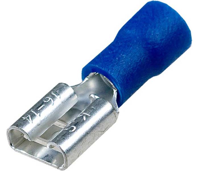
These switches are also called wire crimp terminals. They are used for power conductors with a small cross-section of up to 2.5 mm. The maximum voltage for such a connection is 5 kV. Such a connection will not withstand a more powerful current, so knife terminal blocks are not used in large power plants.
Which terminal blocks are better
In fact, choosing a suitable terminal should be taken very seriously. Especially if there is a need to connect wires with conductors of different metals. During operation, such contacts become very hot and become deformed. This can lead to complete loss of circuit integrity and even a short circuit. It is worth remembering that spring and screw terminal blocks are not suitable for fastening aluminum and copper wiring.
A few words about switch manufacturers
Products from European, Chinese and domestic manufacturers are presented on the shelves of electrical goods stores. As a rule, few ordinary buyers are puzzled by the origin of switches. And in vain. The safety of your property can directly depend on these tiny devices, the size of a fingertip. Don't blindly trust Chinese consumer goods. In most cases, Chinese products do not meet the requirements of domestic standards.

Domestic products are more reliable, but less aesthetically pleasing and technologically advanced. European goods are more expensive, but I bought such a terminal and forgot about it. Manufacturers guarantee long-term and reliable operation of their products. Here are some of them:
LEGRAND
Screw switches from this manufacturer are the most popular product in this category. Brass products are coated with nickel and can reliably withstand powerful temperature changes. These terminals are highly durable and have a wide range of sizes.

WAGO
The products of the French company guarantee a strong connection of wiring of different types and cross-sections. The devices perfectly resist possible vibration and stretching and are installed without special tools. The main material of French terminal blocks is tinned copper, which gives good contact with low resistance. Some models are filled with anti-corrosion gel.

PHOENIX CONTACT
The German manufacturer is distinguished by excellent product quality. It offers more than 200 kinds of different switches for different types connections. Among the presented models there are resistant to high humidity and explosion hazard.

WIEDMULLER
Another European brand offers one and a half hundred models of terminals. The core of the range is made up of screw connections made using DIN technology.

Common problem: how to connect aluminum and copper wire
Residents of Soviet-built houses often face this problem. At that time, almost all wiring was done using aluminum conductors. Modern electricians mainly use copper wire. How to connect aluminum wire to copper? There are skeptics who claim that such a connection is impossible. You shouldn't believe them. If you correctly use the techniques that we present below, the switching will be reliable and durable.
As already mentioned, ordinary twisting will not work for such a connection. The contact between copper and aluminum gets very hot and can damage the insulating layer.
Option 1 – bolt-on
This is a simple and affordable method that uses steel nuts, bolts and washers. Due to the impressive dimensions of such fasteners, it is unlikely to be placed in a modern small junction box. But such switching allows you to combine wiring not only from different metals, but also with different cross-sections. Such connections are easy to disassemble and reassemble if necessary.
Option 2 – “walnut” connection
The name of this connection was invented by electricians because of its external similarity. For fastening, use a special crimp, which is sold in electrical goods stores. The device consists of two dies with grooves for conductors. After fixing the cores, the dies are wrapped with electrical tape.
Content:
Connecting wires is probably the most common task in electrical engineering. Since for one reason or another there is a lack of length of conductors in electrical circuits, it is necessary to connect their parts together. Obviously, this creates contact, which is the root of many electrical problems. And it is not the electrical connections at a specific location on the conductors that are implied in this case.
If the contact is made correctly, the electrical circuit will function properly. But, nevertheless, the phrase “electrical engineering is the science of contacts” has long sounded like a byword. Later in the article we will talk about how to correctly connect the wires so that this connection does not create problems for as long as possible. As well as a number of other issues that are essential for twisting wires and covering other types of their connections.
Twisting, which the PUE is silent about
In addition to the frequently mentioned words about contacts, among electrical workers there is another common phrase that the work performed by electricians and miners is often very similar in its lethal consequences. In particular, for this reason there is a PUE - essentially, a set of laws for everything that has to do with electrical networks. Let's take an interest in the Electrical Installation Rules about how the wires should be connected.
On the one hand, everything is clearly stated:
- crimping;
- welding;
- soldering;
- squeezes -
and these are the four officially acceptable ways to connect the ends of conductors. But they all require something additional from tools or equipment, and in some cases quite complex, because:
- for crimping you will need a special tool that matches the conductors being connected;
- welding is impossible without a welding machine;
- for soldering, a soldering iron is required, as well as the material of the connected cores being suitable for soldering;
- clamps require the use of a special electrical wire connector designed for this purpose.
However, to ensure the connection of electrical wires, you can simply twist their wires together, thus obtaining electrical contact. And, despite the fact that twisting is not indicated in the PUE, the compressive itself reliable connection wires, especially approved in in the prescribed manner, fully corresponds to the letter of the electrical law PUE.
In order for the wires to be twisted reliably, the following conditions must be met:
- the length of twisted conductor strands from the edge of the insulation to the ends is 40–50 mm;
- electrical wires, or rather their contacting conductors, are cleaned with fine-grained emery or a file in order to remove oxide films or insulation residues. You can also use a knife. In this case, movements must be made along the vein. After stripping, it is recommended to evaluate the quality of film removal using a magnifying glass. This will create the best electrical connection;
- In order to properly connect wires without soldering, the twisted ends of the wires must be formed using one of the generally accepted methods. They should be pressed against each other as tightly as possible anywhere in the twist.
- The types of twists used are shown below. These images will help our readers understand how to properly twist.

What is wrong with twisted wire connections and why is it not explicitly mentioned in the PUE? After all, other methods of connecting wires are noticeably inferior to it in ease of installation and minimal cost, for which such a connection of two wires with one core, as well as twisting multi-core wires, is ahead of all. Other methods of connecting electrical wires remain far behind it.
- The main disadvantage of twisting is its weakening over time as a result of repeated thermal expansion of the conductors.
Gradually, due to temperature deformations of the cores, the force pressing them together weakens, and the contact resistance increases. For electrical circuit wires containing low-power consumers such as energy-saving and LED lamps, weakening the contact force will not be dangerous. But for twisting wires in a circuit with electrical heating devices with a power of several kilowatts, from a certain moment an avalanche-like process of deterioration of contact between twisted conductors can begin. Moreover, if such a wiring connection is not noticed in a timely manner, in the best case, either copper wires or aluminum wires, the cores of which are twisted, near it will suffer from damage to the insulation due to high temperature.
- For this reason, the use of twisting in areas with increased fire hazard is prohibited. In these rooms it is necessary to use a more reliable connection of wires.
- Twisting of copper wires with aluminum conductors is not permitted. Just as in any other connection, direct contact between the copper and aluminum cores is not allowed in twisting due to the occurrence of electrochemical processes leading to rapid deterioration of the connection and reinforcement fire danger.
- It is not recommended to reconnect two wires that have been twisted. Only straight strands are twisted after stripping the insulation, and straightening usually breaks even the strands of a stranded conductor.
- Correct twisting can only be achieved for relatively thin conductors. It is not recommended to twist thick single-core wires. To connect wires to each other with a significant thickness of wires, it is better to use crimping them with a sleeve.


Starting from a certain core diameter, it is not possible to twist the wires at all. An example would be a power cable. Therefore, twisting a cable containing 2, 3 or larger number cores, is made with thin copper wire as preparation for a “clean” connection. Then each pair of fixed wires is soldered.


Twisting is half the battle
However, the experiment, which was carried out with twisted stranded conductors, showed the high quality of contact of all wire connections immediately after installation was completed. A hundred twists of sections of stranded copper wire with a cross-section typical for ordinary apartment wiring showed very low contact resistance, which is confirmed by the images below.


Consequently, after twisting, you do about half of the installation work of connecting two conductors. It still remains to refine the resulting connection so that it does not deteriorate over time. And to do this, you need to either create a force that compresses the twisted wires from the outside, or use one of the methods of merging the wires. Merging of conductors is, of course, the best way to ensure minimum resistance at the junction of two, three or more conductors.
The connection of wires by merging the cores is done either by melting them or by soldering them. In any of these options, the lowest value of contact resistance is achieved. But these methods also have significant drawbacks. Both during welding and soldering, the conductors are heated to a temperature that is dangerous for the insulation.
- In order not to spoil it, it is better to hold the twist with pliers immediately behind the edge of the insulation to dissipate heat during welding or soldering and for some time after completion.
- Although there is technology for welding and soldering aluminum conductors, it is still better to deal with copper. But before soldering or welding, the copper core is also cleaned of foreign deposits and degreased.
Welding and soldering eliminates the very concept of contact at the end of the twist, making in this place either a body in the form of a drop (when welding), or filling all the cracks with solder. When connecting wires intended for powerful electrical appliances, welding and soldering are the most The right way conductor connections. However, the experiment, which was carried out on hundreds of twists already shown, did not demonstrate a significant decrease in contact resistance. This is evidenced by the images shown below.


The images provide clear evidence of the same joint properties between conventional and welded stranded wires. But with increasing thickness of the cores, as well as for thick single-core wires, soldering and welding will have an advantage over twisting. If the wires can be connected by twisting, and there is no powerful electrical equipment connected to them, it makes no sense to solder them, much less weld them.
Plug-in connections
The experiments discussed above testify in favor of mechanical fixation of twists. For this purpose, along with sleeves, there are special PPE caps. They make it possible to splice wires, compressing the twist and maintaining the compression force. These are two types of compressions mentioned in the PUE. The first is the sleeve, and the second is the cap. It is screwed all the way onto the stripped conductors. The device, as well as possible types of PPE caps, are shown in the images below.

The abbreviation SIZ reads as:
C – connecting;
I – insulating;
Z – clamp.
Number 1 (SIZ-1) indicates a cap with grooves, and 2 (SIZ-2) indicates the same part with protrusions. Numbers separated by a hyphen indicate the range of wire cross-sections connected to the PPE. The cap is very convenient in that with its use, not only good conductivity of the connection is achieved, but also the ability to separate it. If you need to choose how to connect the conductors to each other, PPE is the best option for home and office electrical networks.
A quick and convenient device that complements separable types of conductor connections is a terminal block. However, its convenience is limited by the load current characteristics. In comparison with the PPE cap, which improves contact resistance, the terminal block worsens it. And it’s very noticeable. To obtain relevant data, a third experiment was made, information about which is shown below. The welded twists were cut off. The ends of the wires are inserted into the terminal blocks.


- The contact resistance of the terminal block is an order of magnitude greater than that of the twist.
But it is not only the most acceptable solution for connecting low-current electrical wiring in an apartment and office.
- The terminal block is a connecting element between wires with copper and aluminum conductors.
- It is convenient to use for connecting wires with different cross sections.
- For copper conductors, it is recommended to apply contact paste before inserting them into the terminal block.
- Aluminum conductors must be cleaned of oxide film before inserting into the terminal block.
Three types of these connectors are used:
In order for the wire to be inserted into the terminal block without effort and, if necessary, just as easily removed from it, a design with a lever is used, which creates a force in the connection to fix the core. WAGO terminal blocks and their analogs are made on this principle.
A very common type of compression is the screw connection. The designs of many terminal blocks, connecting blocks and sleeves are based on this connection. The screw connection allows you to obtain the greatest force compressing the connected cores. But in order to ensure that such a connection does not weaken over time due to vibrations and temperature deformations, a force is applied to it using a spring, which creates a holding voltage.


- Screw clamps are the most effective connection of a single-core wire with a stranded wire, wires of different diameters, including aluminum and copper.
- Since screws, nuts and washers are always available to everyone who has connected their profession or hobby with technology and works with their own hands, if necessary, connecting two wires with their help will not be difficult. However, this is done according to the rules that are illustrated in the image below.

- When using screw clamps, it is necessary to remember that the quality of contact is primarily determined by the area of the contacting surfaces. And it decreases as the core diameter increases. In this case, no efforts of screw clamps will help. For large core diameters, contact pastes and gels must be used. But in this case, soldering and welding will still provide more reliable contact than a screw connection.
Correct connection of wires is the key safe work electrical networks. We must not forget how to twist correctly, choose the optimal type of connection, and also perform it correctly.
In the article we will talk about methods for connecting wires in junction boxes, and talk about preparing conductors for connecting household appliances and installation products.
Electrical wiring of residential premises consists of many elements, these are various current-carrying conductors (cables), protective devices, electrical installation products, and individual current consumers. In order to assemble all the components of the system into a single circuit and at the same time make the power supply functional and safe, it is necessary to qualitatively connect them together, or, as they say, switch them (switching refers to the processes that occur when electrical circuits are closed or opened).
At first glance, it may seem to an unprepared person that there shouldn’t be anything complicated here. But when working with electricians “on a whim,” it doesn’t matter whether we’re moving a single outlet, connecting a lamp, or assembling a complex control system, we take a serious risk. Experienced electricians know that electrical installation is primarily a “struggle for contact,” since it is an open circuit, and not a short circuit, that is the most common problem encountered. Obviously, the connection points in the circuit (terminals, twists) are the most vulnerable, since at these points the mechanical density of the contact can weaken (the contact area decreases), and an oxide film with a very high resistance forms on the conductors over time. Poor contact causes heating of current-carrying conductors and sparking at switching points - these are the consequences of the occurrence of transient contact resistance. Complete burnout of the wire and loss of power to the area when household appliances do not work or the light goes out is unpleasant, but the problem is solved. It’s worse if the insulation of the wires heats up and breaks down, which can lead to electric shock or fire.

Recently, the load on wiring has increased significantly, so switching is now subject to even more stringent fire and electrical safety requirements. However, if previously there were not many connection options, now reliable modern devices have appeared that make wiring easier. In addition to welding and soldering with subsequent tape insulation of the twist, PPE caps, various terminal screw and spring blocks, all kinds of insulated and open lugs, and branch clamps can be used in a household network. These products will help to qualitatively connect wires in junction boxes, assemble a distribution board, connect household appliances and lighting fixtures, sockets and switches.
There are several key objective factors that influence the choice of switching method, or the use of specific devices. Let's just list the main ones:
- power and number of consumers (read: total cross-section of conductors);
- material of current-carrying conductors (copper or aluminum);
- cable type (flat or round, hard or soft stranded, single or double insulated);
- purpose of the node (group or single branch, end connection);
- the presence of movement of wires or vibrations near them;
- elevated temperature, humidity;
- indoor or outdoor use.
Connecting wires in junction boxes
According to the provisions of the PUE, branching of household network wires can only be carried out in a distribution (junction) box. During operation of the wiring, junction boxes allow you to quickly get to the ends of any individual branch and, if necessary, detect which of them is broken or has a short circuit. You can also always inspect the condition of the contacts inside the box and make them Maintenance. Modern PVC boxes are used for open and hidden wiring; they have sufficient reliability and expanded functionality: they can be easily installed on various surfaces and are convenient for electrical installation manipulations.
In order to always have access to the connected wires, all distribution boxes are located on free sections of the walls; it is most rational to install them on the side of the corridors, for example, above the door of the powered room. Naturally, boxes cannot be tightly plastered or sewn inside building frames; the permissible decorative maximum is a thin-layer finish on top of the lid (paint, wallpaper, decorative plaster).

For the arrangement of lighting and power circuits (outputs and sockets), it is recommended to use separate distribution boxes for each room. Such divided power allows you to make the electrical wiring of your home more balanced and safe, since the “lights” and “sockets” differ in workloads and operating conditions, and they are subject to different requirements. Moreover, it is much easier to modernize or repair the wiring later, and not always all the wires in a room can be properly laid out in one housing.
Switching wires in any distribution box can be carried out according to the same principle. In most cases, “twisting” is initially used, but simply wrapping the conductors with electrical tape is not enough - it must be reinforced with additional operations that are designed to increase the contact area of the connected current-carrying conductors and reduce the oxidation of materials. Clause 2.1.21 of the PUE offers the following options:
- soldering
- welding
- crimping
- crimping (bolts, screws, etc.)
Wire crimping
The essence of this method is that twisted wires are inserted into a special metal sleeve-tip, which is compressed with hand pliers, a mechanical or hydraulic press. Crimping can be done either by local pressing or by continuous compression. This connection of wires is considered one of the most reliable. Crimping allows you to compress the cores very tightly, increasing the contact area, mechanical strength of such commutation is the highest. This method is used for both copper and aluminum wires.

The crimping process consists of several operations, each of which has its own nuances:
- The wires are freed from insulation 20-40 mm from the edge, depending on the working length of the sleeve.
- The veins are cleaned with a brush or emery until shiny.
- Using pliers, a tight twist is made.
- Based on the total twist section, a GAO sleeve with the required internal diameter is selected, as well as a suitable punch and die.
- The inside of the sleeve is treated with quartz vaseline paste (if it comes “dry” from the factory).
- The twist is inserted into the sleeve.
- The twist is compressed using press pliers. It is necessary that the tool rig is completely closed.
- The quality of the connection is checked - the wires should not move in the tip.
- The sleeve of the connected conductors is wrapped in three layers of insulating tape; for a tip thickness of up to 9 mm, a polyethylene insulating cap can be used.

Conductor crimping
Crimping of conductors can be done using terminal blocks, PPE caps or WAGO clamps.
The terminal block housing is made of plastic; inside it there are sockets with threads and clamping screws. The wires can be inserted under single screws of the terminal towards each other, or one conductor passes through the entire block and is fixed with two screws. Some distribution boxes are equipped with standard terminal blocks.

A clear advantage of switching on a terminal block is the ability to connect copper and aluminum wires, which in this case do not have direct contact. The disadvantage is the need to tighten the bolt clamp if aluminum conductors are used.
PPE caps (connecting insulating clips) are also made of durable non-flammable polymer, which, being an insulator, provides mechanical and fire protection. They are forcefully wound onto the twisted conductors, then the conical metal spring located inside the cap moves apart and compresses the current-carrying conductors. As a rule, the internal cavity of the PPE is treated with a paste that prevents oxidation.

WAGO terminals for junction boxes are screwless, here the compression is performed by a spring, you only need to insert the stripped wire into the terminal. These terminal blocks are designed to connect up to eight wires with a cross-section of 1-2.5 mm 2 or three wires with a cross-section from 2.5 to 6 mm 2, while the spring acts on the conductor with a force suitable for each wire. The clamps function normally at operating currents up to 41 A for 6 squares, 32 A for 4 squares and 25 A for 2.5 squares. Interestingly, WAGO universal clamps allow you to connect wires of different sections (from 0.75 to 4 mm2) in one housing.

These devices can be designed for a hard conductor, or for a soft stranded one. Due to the fact that there is no direct contact of the connected conductors, it is possible to connect copper and aluminum wires, and there is no need to regularly check the compression of aluminum. Inside, WAGO terminal blocks also have a paste that destroys the oxide film and improves contact, but the clamps for copper conductors are not filled with contact paste. It is very easy to work with such connecting products, they are quickly installed, without the use of additional tools, they are compact and reliable. It must be said that WAGO is not the only company producing screwless spring-loaded terminal blocks.

Whatever type of crimping device is used, it is necessary to accurately select it according to the cross-section of the individual conductor or strand, since a terminal that is too large may not provide normal contact. In this case, you cannot always trust the markings - it is better to check the compliance of fasteners and conductors on site. During installation, we recommend having an assortment of crimp terminal blocks available according to standard sizes. Please note that to work with aluminum it is necessary to use contact gel; copper and aluminum conductors cannot be connected in one twist. After crimping, it is always necessary to check the strength of fixation of the cores in the terminal.
Soldering wires
Due to the technological complexity, this connection method is used quite rarely, mainly when for some reason it is impossible to use crimping, crimping or welding. You can solder wires made of aluminum and copper, you just need to choose the right solder. For branching wires with a cross-section of up to 6-10 mm2, a regular soldering iron is suitable, but larger wires will have to be heated with a portable one. gas burner(propane + oxygen). For soldering, it is necessary to use flux in the form of rosin or its alcohol solution.
The advantages of soldering are the high reliability of the connection compared to crimping (in particular, we have an increased contact area). This method is also quite inexpensive. The disadvantages of switching construction wires by soldering include the duration of the work and the technical complexity of the process.

The soldering of conductors looks like this:
- the wires are stripped of insulation;
- the wires are sanded with emery to a metallic shine;
- a twist is made 50-70 mm long;
- The core is heated with a torch flame or a soldering iron;
- the metal is coated with flux;
- V work area introduce solder or immerse the hot twist in a bath of molten solder for 1-2 seconds;
- After cooling, the soldered twist is insulated with electrical tape or polymer caps.
Welding
Most often, electricians use contact heating welding to reliably connect wires in a distribution box. You can weld twists with a total cross-section of up to 25 mm 2 . Under the influence electric arc at the end of the twist, a fusion of the metal of several wires into a single drop is formed, and then the current during operation of the electrical circuit does not even flow through the body of the twist, but through the formed monolith. If everything is done correctly, the connection is no less reliable than a solid wire. This method has no technological or operational disadvantages, the only thing is that you need to purchase a suitable welding machine.
Welding of copper conductors is carried out using direct or alternating current with a voltage from 12 to 36 V. If we talk about factory welding units, it is better to use inverter devices with sensitive adjustment of the welding current, which are lightweight and small in size (during operation they are sometimes worn on the shoulder) , can be powered from a household network. In addition, inverters provide good arc stability at low welding currents. Due to the high cost of inverters, very often electricians use homemade welding machines made from a transformer with a power of more than 500 W, with a secondary winding voltage of 12-36 volts. The ground and electrode holder are connected to the secondary winding. The electrode itself for welding copper conductors must be infusible - carbon, this is a factory-coated "pencil" or homemade element from similar material.

If a factory inverter is used for welding wires, then for wires of different sections it is recommended to set the following operating current indicators: 70-90 amperes is suitable for connecting two or three wires with a cross-section of 1.5 square meters, wires with a cross-section of 2.5 mm 2 are welded at 80-120 amperes These indicators are approximate, since the exact composition of the core may vary from one manufacturer to another - it is recommended to test the device and a certain current strength on scraps of conductors. Correctly selected indicators are when the arc is stable and the electrode on the twist does not stick.
The wire welding process includes the following operations:
- the conductors are cleared of insulation (about 40-50 mm);
- a tight twist is made with pliers, its end is trimmed so that the ends of the wires have the same length;
- a ground clamp is connected to the twist;
- the carbon electrode is brought to the end of the twist for 1-2 seconds (so that the insulation does not melt, but a solid copper ball is formed;
- after cooling, the welded twist is insulated with electrical tape, heat-shrink tubing or a plastic tip.

When connecting wires, you should follow safety precautions and take fire precautions, as for any welding work. It is recommended to use a welding mask or special glasses with a light filter; welding gloves or gloves will not be superfluous.
Connecting wires to electrical equipment terminals
Connecting household appliances and various electrical installation products is also an important stage in wiring switching. From reliability electrical connections These nodes depend on the performance of consumers, as well as user protection and fire safety.
The technology for connecting current-carrying conductors to equipment is regulated by the PUE, current SNiPs, as well as “Instructions for terminating, connecting and branching aluminum and copper conductors of insulated wires and cables and connecting them to the contact terminals of electrical devices.” Just like branching conductors in distribution boxes, soldering, welding, crimping, screw or spring crimping are used for termination and connection. One method or another is selected primarily depending on the design of the equipment, as well as on the properties of the current-carrying conductor.
Screw crimping is used in most types of modern equipment. Screw terminals are found in sockets and switches, chandeliers and lamps, in various household appliances (built-in fan, air conditioner, hob). Crimp sockets are used to supply elements of the distribution board: circuit breakers, RCDs, electric meters, and switching busbars with screw terminals are also used here.

It should be noted that convenient spring-loaded terminal blocks can also be used to connect equipment. For example, very often switches are equipped with screwless terminals; WAGO produces a special series of clamps for connecting chandeliers and lamps, as well as for switching in ASUs (terminals mounted on a DIN rail).
Please note that to connect using the crimp method, soft stranded conductors must be terminated with insulated lugs (connectors). For rigid monolithic cores, connectors are not needed. If you do not use lugs, then the soft core should be tightly twisted and tinned with solder before connecting. The size of the tip is selected depending on the cross-section of the conductor, and the geometry of the contact part is selected depending on the type of terminal on the connected device and the operating features. For example, for a clamping tunnel socket, a connector in the form of a pin is used; for fixing with a nut on a bolt, a ring or fork connector is used. In turn, the fork tip is not recommended for use if the device is moving or vibration is possible in the switching area.

If it is necessary to clamp a rigid single-wire conductor (copper or aluminum) with a cross-section of up to 10 mm 2 under the bolt, then it can be bent into a ring of a suitable radius using pliers. The ring is cleaned from the oxide film with glass sandpaper or sandpaper, lubricated with quartz-vaseline gel and put on the bolt (the ring should wrap around the bolt clockwise), after which it is covered with an asterisk washer (prevents the conductor from being squeezed out), a groover (springs the connection, prevents it from unwinding when vibrations), and the assembly clamp is tightened tightly with a nut. If a large cross-section core (from 10 mm2) must be clamped under the bolt, then a metal sleeve with a ring is placed on the conductor using the crimping method.

Switching wires is a very responsible job, and the process of assembling the circuit has a lot of nuances, which for convenience should be combined into one list:
- Strip the wires using special pliers, since stripping the insulation with a knife often reduces the cross-section of the wire.
- Always remove the oxide film from the conductor. Use glass sandpaper or sandpaper, use special liquids and contact paste.
- Make the twist a couple of centimeters longer, and then cut off the excess.
- Select the diameter of the sleeve or tip as accurately as possible.
- Place the conductor under the terminal or sleeve/tip all the way to the insulation.
- Make sure that the wire insulation does not get under the clamp.
- If possible, insert and clamp into the tunnel screw terminal not a single soft core, but a double core.
- When using electrical tape, wind it with overlapping turns in three layers, be sure to go to the insulating sheath of the conductor. Electrical tape can be replaced with heat shrink or plastic caps.
- Be sure to wrap screw terminal blocks with electrical tape.
- Always mechanically check the strength of the connection - tug on the conductors.
- Never connect copper and aluminum directly.
- Securely secure the cable near the patching area so that the wire is not pulled down and there is no mechanical stress on the connection.
- Use color coding of conductors, for example, in the entire intra-house network, the brown conductor will be the phase, the blue conductor will be the neutral, and the yellow conductor will be the ground.
- For the installation of all devices, adopt a single connection diagram (for example, the phase on the sockets is clamped on the right terminal, and the neutral - not on the left).
- Label both ends of all wires yourself - ballpoint pen on the outer shell, at a distance of 100-150 mm from the edge of the conductor, write its purpose (for example, “pink kitchen desk” or “bedroom light”). You can also use tags or pieces of masking tape.
- Leave a supply of wires convenient for installation. For distribution boxes, sockets and switches, the normal end length will be 100-200 mm. To switch the switchboard, you may need wires up to one meter long so that you can run some of them from the bottom of the box, and some from the top.
- Bring external cable channels close to the distribution boxes; it is better to insert round corrugation or pipes a few millimeters into the housing.
- We connect sockets in parallel, and switches in series. The switch must break a phase, not a zero.
- Compress all the wires of one connected twist into a bundle and secure it with electrical tape. Inside the box, route the insulated connections to maximum distance between themselves.
- Use only certified materials and specialized tools.

In conclusion, I would like to once again note the importance of high-quality performance of switching work. In fact, the technologies used are quite simple, you just need to make them a habit, and then the “installation culture” will appear by itself, and the wiring will be reliable and durable.
Cut the cable at an angle so that the end is tapered rather than blunt. Leave the wire closest to the cut point about 7-8 cm longer than the other two wires. Straighten the stiff wire and make a small loop at the end.
Pass the wire through the loop and wrap it around the stiff wire. Start wrapping the electrical tape around the cable, over the connection. Wrap the tape tightly in a spiral until you get it over the wires. Each successive winding overlaps the previous one, reducing the likelihood that the edge of the tape will catch on something as you pull it through obstacles. Copper wire is not as stiff and is more likely to come free from the connection in the style shown, so this method should not be used with it.
Connection of two flexible wires
If you are using copper wire as a fishing tool, use Western Union connection. Start with two L's, then wrap each wire around the other without looping them over themselves. The recording step is the same for both methods.

How to connect wires correctly: 4 main ways
Methods of connecting wires are regulated by the Electrical Installation Rules. According to their latest edition, the following options can be used for connection:
- soldering;
- welding;
- crimping;
- squeeze
Nevertheless, many electricians still use one of the most common connection methods - twisting. According to current rules, this is not a complete process; it must be followed by soldering, welding or clamping. The soldering method is not given below.
How to choose a wire connection method
The choice of the optimal option depends not only on the personal preferences of the master, but also on a number of other factors. For example, when combining aluminum and copper, it is important to consider the possible oxidation process. Also, not all methods are suitable for a large number of wires in a connection. The load in the circuit, cross-section and number of cores, etc. also have an impact.
Connecting wires by welding
Compared to soldering, welding is an even more reliable connection method, but it is rarely used as a household method, since it requires a welding machine, personal protective equipment and welding skills.
The welding technique is approximately the same as in the case of soldering, but before the procedure it is necessary to take the free ends of the two wires, straighten them and press them parallel to each other in order to better form a melt ball.

The welding area must cool naturally before insulation is carried out. Submerging the wire in cold water causes microcracks to appear.
The disadvantages of the method include:
- high cost of equipment;
- the need for relevant skills;
- time costs.
Pressure testing of connections
Crimping ensures high-quality installation and reliable insulation. For this method, special tubular sleeves are used, which are selected in size depending on the cross-section of the wire. Connecting wires in this way requires a crimping tool: pliers or a crimping press.

After cutting the wire, that is, removing the insulation and stripping the ends, quartz-vaseline paste is applied to the wires, a connector is put on and crimped. Wires can be inserted from opposite or one side. When using a high-quality and professional tool, you can crimp the wire in one go. After this, the usual insulation of the joint is performed.
Among the disadvantages of this method are:
- the inability to reuse the connector, as it is deformed during crimping;
- connecting copper and aluminum wires in this way is only possible when using a special sleeve, which is difficult to find on sale;
- takes enough a large number of time.
Connecting wires using compression
Wire compression can be done different ways, some of which are more preferable, others less.
Connecting insulating clamps resemble crimping sleeves, with the difference that inside they have a steel wire coiled into a spiral, which protects the wires from oxidation and presses them tightly together. The connections are easy to use, and you can use clamps of different colors if the wires do not have color coding, in order to mark zero, phase and ground.
The use of clamps is limited by the number of wires connected: they are suitable for two wires with a cross-section of 4 mm2 or four with a cross-section of 1.5 mm2. Over time, the spring weakens, causing resistance to increase and voltage loss in the network to occur. It is impossible to combine wires from different materials with this connection method.
Using a short bolt, three washers, a nut and electrical tape, you can quickly and cost-effectively connect wires from any materials, but the junction is very bulky, so this option cannot be used in a junction box.
Screw terminals are convenient for connecting lamps, sockets and switches. They allow you to connect copper and aluminum wires without additional insulation. The disadvantages include the need to maintain connections: the screws need to be tightened periodically.
Using modern terminal blocks is the simplest, fastest and convenient way connections of wires of any type. Due to small size they easily fit into the junction box; there are different options for terminals for wires with different cross-sections. They provide high quality connections and high installation speed. One of the disadvantages is the possibility of poor quality pads, which can cause disruptions in the network. Working with them requires care and attention to avoid damaging the wires.

When choosing any of the above options, you must ensure safety and reliability electrical network. It is very important that all wire connections, regardless of the method of their joining, be provided with easy access for inspection and maintenance during operation.
Wire connection methods
Hello, dear readers! This article will describe the different wiring methods, their pros and cons. The most important thing during electrical installation is to follow safety rules and PUE (Electrical Installation Rules). 1. Twist. The most common wire connection. Fast and cheap. You need to remove the insulation and use pliers to twist the wires into a bundle. The twist is made with high quality if its length is at least 5 cm, the strands fit tightly to each other and are not damaged. But this type of connection in this form is contrary to the rules, unlike those below. But we are all human and we all violate something.

2. Welding. This is a combined version of the same twist, but welded at the end. This type of twisting meets the standards and can be used for electrical installation. Welding can be done using a low voltage transformer or a low current inverter. In this case, a graphite rod acts as an electrode.

3. Screw terminals type ZVI 20. A short twist is made, after which a clamp is put on it. The clamp has two screws that compress the wires together and press them against the body. But like any screw connection, the fixation may become loose over time and the screws will need to be tightened. This connection is best used in unloaded circuits with free access to distribution boxes.