Instructions for using a multimeter. How to measure voltage with a multimeter
We will send the material to you by e-mail
When you need to measure current, voltage or check a wire for integrity, you can use a separate device or use a multimeter for each type of work. It is very useful not only for professionals, but also for beginners in this matter. Let's look at how to use it correctly and what types exist.
A multimeter is a universal device for measuring voltage, current, resistance, and it is also possible to determine the integrity of the wire. Modern models have greater functionality; to use them you should know how to use a multimeter correctly.
Analog option
There are two options for the multimeter:
- analog;
- digital.
Analog
In analogue, the reading is looked at by the movement of the arrow relative to the scale, where there are special symbols (voltage, current, resistance). If you use a Chinese model, you may experience inconvenience due to the way the scale is applied. Although there is a significant error in the results, this design of the device is still popular due to its affordable cost.If you require accurate measurement readings, you must use a trim resistor.
Digital
All data is displayed on the screen, which can be LED or LCD. The ease of use and accuracy of readings attracts consumers.

New graphical multimeters can be compared to simple oscilloscopes because they display the waveform. And some developments may be compatible with a computer, and then the device can be controlled through it.
That is, the multimeter incorporates more and more functions, allowing you to simplify your work and replace several devices at once.
What can be measured with the device All types of multimeters are capable of measuring current and resistance, as well as voltage in a circuit.
Voltage measures how much electricity flows through a circuit. Indicated by the sign "V". Current represents the intensity with which electricity flows (“A”). And resistance shows how much difficulty electricity encounters along the path of the circuit.
Some models are capable of testing diodes, which act as valves where the current flows in one direction. The latest models additionally measure temperature, frequency of an electrical signal, measurement of transistor, capacitor, and inductance parameters. Each measurement indicator has its own designation.

In order to understand how to use a multimeter correctly, you need to know what it consists of.
What does the device consist of?
The set of the analog multimeter includes a pointer magnetoelectric device, a set of additional resistors and probes. If it is necessary to check variable voltage and current, the device is connected via rectifier diodes.
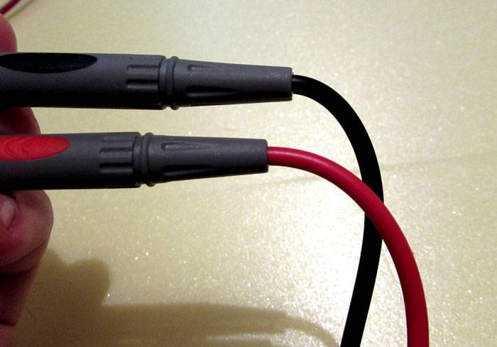
Let's look at the digital model in more detail, and we will carry out further measurements with it, since the functionality is much higher and the readings are more accurate. The basic package of the digital model also includes probes, which must be strengthened before use. To do this, fix the entry points of the wires into the plastic tube holders. This is necessary so that when measuring the wires in the bends of the probes are not damaged.
The remaining unoccupied socket is used to measure alternating current with a limit of up to ten amperes and without a fuse.

They work with a multimeter using a round arrow button, which by default is set to the “Off” position. It should be rotated to the desired position.
Having studied the main buttons and connectors of a digital multimeter, we will analyze in detail each measurement method.
In order to understand how to check the resistance with a multimeter, we switch the device to the “K” or “M” mode (Kilo-ohms or Mega-ohms). The choice of mode depends on the required measurement limit.
In order to learn how to take readings, let's take the simplest resistor 82R, the resistance of which should be equal to 82 Ohms. We apply one probe to one end, the second to the second. Deviations within 10% are considered normal. That is, if your device shows 81.9, then everything is in order.

Thus, answering the question of how to measure resistance with a multimeter, it is enough to simply lean the probes against the open (bare) ends of the device from which you want to take readings. Often a capacitor fails to work; to determine its serviceability, it is necessary to check the capacitor with a multimeter.
How to check the functionality of a capacitor: instructions
Based on the type of mounting, all capacitors can be divided into polar and non-polar. The polar ones include electric ones, which we will check. When checking this device, do not forget that it only passes alternating current, and direct current passes through it for only a few seconds at the beginning of operation. Using a multimeter, you can check a capacitor with a capacity of 0.25 μ Farad.

Sequencing:
- Now you need to set the knob to measure resistance or test the circuit. In these modes, the device generates direct current. At that moment in time, when current still flows through the capacitor, the resistance reading will be minimal.
- We press the probes to the terminals of the capacitor. In this case, while the readings are being taken, the capacitor will be charged from the device.
- At the moment of touch, the current resistance will be small; as you continue to hold the probes, the readings will increase. We wait until the numbers on the screen become large. If no failures occurred during the measurement process, then the capacitor is operational.

If at the very beginning, when you just touched the leads of the capacitor with the probes, the multimeter showed zero resistance and started beeping, a short circuit has occurred.
Checking voltage and current
When taking current readings, it is necessary to connect the probes in series with the load, unlike other quantities where the connection occurs in parallel.

Let's look at how to measure current with a multimeter using the example of a computer cooler. This indicator is measured in amperes, so we set the indicator on the device to 12 W, and change the handle to measure direct current. The limit can be set to 20 Amp. We assemble according to the diagram and monitor the device screen. If they match, then everything works properly.

If you need to check the alternating voltage, then you should set the knob on the multimeter to the appropriate indicator. And the measurements themselves are carried out in the same way.
Now let's look at how to measure voltage with a multimeter in an outlet. We also use a digital device, since it already belongs to professional equipment. The measurement process itself is extremely simple, you need to insert the probes into the socket and turn the switch to 750 Volts. Deviations from the norm of 10% when measuring are considered normal, so you should not expect to see exactly 220 W.
Note! Don't forget about safety precautions, so before plugging the device into a socket, check the integrity of the insulation of the probes.
It is important not to confuse the operating mode; if you set it to resistance, you will simply ruin the device.

Any home DIYer who has at least basic knowledge of electrical engineering should know how to use a multimeter (tester). Despite the fact that a modern device has a lot of functions, capabilities and measurement limits, it is quite simple. The main thing is to learn how to correctly connect the measuring probes, understand the meaning of all the symbols printed on the front panel and be able to work with different ranges and modes, depending on the situation. To understand the details of this issue, we suggest using the following instructions for using testers in practice. As an example, in this article we will look at a digital device, which will be much easier to work with compared to a dial multimeter. If you have not yet purchased the device, be sure to check out ours.
What is important to know about the tester device
Before you start making any electrical measurements, it is worth understanding what the device itself is and what its functions are. All information is printed on the front panel. You can learn how to use a multimeter of the selected model based on the following generally accepted notations:
- ON/OFF – button to turn the device on/off (on some testers it may not be present; in this case, the device will be turned on by turning the range switch);
- DCA (or A-) – direct current;
- ADCA – alternating current;
- ACV (V~)/DCV (V-) – alternating/direct voltage;
- Ω – resistance.

To take readings, you need to use a rotary switch, which allows you to set different operating modes of the multimeter and select the measurement range.
One of the important points in mastering the question of how to use a digital multimeter is the correct connection of the test leads to the appropriate connectors. The correctness of the measurements taken will depend on this. In order not to make mistakes, there are simple rules:

COM - black size on the left, universal connector in the center, connector for measuring high currents - on the right
- COM connector is common, it is used to connect the negative black measuring wire;
- to connect the red positive probe, one of the sockets for measuring voltage (V), resistance (Ω), current (mA, A) can be used, while it should be taken into account that, as a rule, there are two current sockets (for working with low-current circuits and with current up to 10/20 A depending on the tester model).
But it is also necessary to take into account that when measuring voltage or current, measuring probes installed in reverse will lead to a change in the polarity of the received data, which will be reflected on the display by the appearance of the “-” sign. The digital values will be correct. This is how digital devices differ from analog ones. In the latter, the arrow most often goes beyond the scale, and in some cases such work can lead to damage to the device.
Instructions on how to use a multimeter for dummies
The main purpose of any tester is to measure electrical quantities. When measuring current, a device connected to a circuit is connected to an open circuit (in series), and in order to use the tester as a voltmeter, it is connected to the circuit in parallel.
Using a Digital Multimeter to Measure Voltage
The method for measuring DC voltage is quite simple.
- Using the rotary switch, select the type of quantity being measured and the measurement limit.
- Setting the limit can be done after the user has determined what the approximate value of the measured voltage is. A hint can be the markings on batteries or parts of electrical circuits. The limit should always be greater than the measured value in order to prevent overloading of the device elements and its failure.
- In accordance with the instruction manual, the test leads must be connected to the terminals/terminals (black - to “minus”, red - to “plus”).
- We get the DC voltage value on the tester display.

measure the voltage of the electrical network
Another way to determine the measurement limit is to initially set the connected device to the largest possible measurement limit. Then, after taking readings, to improve the accuracy of the data obtained, you can reduce the limit to the nearest higher value, comparing it with the measured readings. There are no fundamental differences in how to take data on DC and AC voltage. The only difference is to switch the tester to the desired mode. The above algorithm then works.
Practical example of using the voltage measurement function

One of the most common operations in which you need to measure voltage is checking the condition of batteries. Moreover, it can be either an ordinary finger-type or an automobile one. In any case, it would be useful for a home craftsman to know how to properly use a multimeter in such a situation. If we are talking about AA batteries, measurements are performed as follows: the switch is set to the desired DC voltage limit. The resulting value must correspond to the nominal value. A deviation of ±10% from the nominal value is considered normal.
How to measure current
Before using a tester (or multimeter) to measure current, you need to decide whether the device under test operates with alternating or direct current. In addition, you need to know the approximate value that will be obtained as a result. This will allow you to correctly select the mA or 10/20 A socket used for work. Even if you have no idea how much current you will get in the end, solving the problem is simple. It is enough to first set the maximum limit, and then, based on the data obtained, if necessary, re-measure the value by moving the measuring probe and switch to a smaller range.
Testing circuits with a multimeter
Continuity testing is one of the main modes, which is often used in household use of multimeters to determine breaks or short circuits in a circuit. It is enough just to set the desired mode on the tester, turn off the power (including low-power ones such as batteries), discharge the capacitors, install the measuring probes and connect them to the required points of the electrical circuit.
For the convenience of the user, in the absence of breaks, most models are equipped with a buzzer, the signal of which makes it easy to navigate the results. In addition, in this case the resistance value or “0” will be displayed on the display. The absence of sound or the display of “1” on the screen will mean an open circuit in the circuit being tested. You can find out more about the continuity of wires, switches and other devices in.
Resistance measurement
A huge “advantage” of the resistance measurement operation itself is that when measuring it using a multimeter, it is almost impossible to damage the device or part in the equipment being repaired. To perform the operation correctly, you need:
- set the rotary switch to sector Ω,
- turn off the power, remove the batteries, accumulator,
- select the most suitable measurement limit,
- connect to the terminals of the circuit element being measured,
- take readings.

The whole procedure is quite standard. The only important difference is that after taking measurements, you may see "OVER", "1" or "OL" on the display. This means that an overload has occurred and the measurements must be repeated by switching the device to a larger range. Also, the display may show “0”, which means that the limits need to be lowered. To successfully use the resistance measurement function, knowledge of these simple rules will be quite enough.
Capacitance measurement
Radio amateurs and electricians who repair household appliances often need to measure the capacitance of capacitors. This issue is no less relevant for machine tool owners who periodically need to select the capacitor capacity when connecting a three-phase motor to a single-phase network to optimize the operation of the motor. These operations are performed by analogy with measuring resistance.
An important difference lies not only in the position of the switch, which must be set to the appropriate mode and range, but also in the mandatory pre-discharge of the capacitors. Otherwise, at a minimum, incorrect readings will be obtained (when working with low-capacity elements), and at maximum, the device will fail. As a rule, for operation in capacitance measurement mode, manufacturers provide separate sockets in the multimeter.
Detailed video instructions
In the first part of the video you will find general information on how to use a multimeter and learn how to measure DC and AC voltage.
After watching the second part, you will learn how to measure resistance, test circuits, check diodes, use the built-in generator, and also measure the amount of electric current.
Multimeter safety
There are several potentially dangerous situations in which simple user carelessness can lead to instrument failure and failure of the equipment being tested.
- If it is necessary to measure voltage, the probes are installed correctly, and the switch is in any position other than voltage (on resistance, current).
- If you want to measure current, the test probe will be installed in the low current socket and the switch will be set to measure high current.
- When testing or measuring resistance in equipment, it is necessary to remove all batteries installed in it, since operation in this mode will damage the device.
- When operating in the continuity mode, if there are charged capacitors (capacitors) in the circuit, it is necessary to discharge them by short-circuiting them. When operating circuits with high-capacity elements, discharge can be performed through an incandescent lamp. Ignoring this rule may cause the multimeter to burn out.
All of the above situations lead not only to material losses, but also to increased danger for the person working with the tester. If you use the multimeter incorrectly, working with electricity can lead to accidental contact with live parts under high voltage, and this is already life-threatening. Otherwise, it is enough to follow simple rules and laws of electrical engineering to easily master working with a multimeter in all its modes and successfully carry out the necessary measurements without turning to specialists.
An experienced electrician who often works with networks and repairs various devices must have a multimeter in his arsenal. This device is a device that combines the functions of an ohmmeter, ammeter and voltmeter. In this article we will tell youwhat they are and what needs to be taken into account when working with the device.
There are two types of testers - electronic (digital) and analog. Nowadays, analogue ones are practically not used due to their large weight and dimensions. They have long been replaced by digital devices - they are small, convenient and allow you to take measurements with high measurement accuracy. They are not difficult to use, especially if you read the instructions and remember the connection rules.
Basic symbols on a classic multimeter
- OFF. Indicates that the tester is turned off and does not consume power.
- ACV. AC mode is enabled.
- DCV. Constant current mode is enabled.
- DCA. DC current measurement.
- Ω. Conductor resistance measurement mode.
Switching modes occurs by turning the switch to the desired position.On the bottom or right side, you will find three connectors that are used to connect test leads. To get it rightyou need to understand their operating modes.
Attention:The black cable is always plugged into the com connector. Red is plugged into the socket VΩmA, if work is carried out with currents up to 200 mA or a multimeter is used to measure resistance. If work is carried out with currents more powerful than 200 mA, then the cable is connected to socket 10 ADC.
When working, you must take this requirement into account. If you apply high currents to the VΩmA socket, the device will simply fail. At best, the fuse will blow, at worst, the system board will be damaged.
How to measure voltage correctly
To understand how to use a dial multimeter to measure the voltage, you should watch the video at the bottom of the page. The principle is simple - you turn on the probes, select the voltage and calculate the value based on the deviation of the arrow. Using an electronic device is even easier - you don't need to count anything. For example, you need to measure the voltage in an outlet. You select the ACV (alternating current) mode, turn on the black probe in Com, the red probe inVΩmA. You assume that the network is 220 volts, not 380, so you set the switch to the nearest value. If it is not clear what the voltage is in the network, then set the maximum value and lower it little by little.
 Classic dial multimeter
 For example, your multimeter has three settings - 5 volts, 200 volts and 700 volts. You decide to measure the voltage in the outlet, but you don’t know what the voltage is. First you set it to 700 volts and take a reading. The device shows 235 volts. You realize that measurements should be taken in a different range and switch to 200. The next measurement shows 223 volts, which is the most accurate value.
If you are measuring voltage in a DC network, then you need to switch the knob to the appropriate position. AC symbol on multimeter — DCV. Next, everything is done in the same way as in the case of measurements with alternating current with the selection of the most accurate value. Measurements are made with a parallel connection, not a serial one, that is, on two phases, not on one. It will not be possible to remove the voltage from one wire.
Attention:Be careful when working with electricity. Think about what you are doing to avoid causing a short circuit or touching exposed wires with probes.
If you need to find a phase, you can simply use an indicator screwdriver - it helps to find the phase in 220 volt networks without using a device. But if you are repairing wiring, then you won’t be able to get by with just a screwdriver - the phase may be everywhere, and the zero may fall off. But use a multimeter you should be able to do it anyway - these are the basics for any electrician.
How to measure current correctly
Measuring current begins with determining what kind of current you have to work with: alternating or direct. You need to set the switch to the desired position. Then determine the approximate current strength in the circuit. Connect the second probe to the corresponding connector ( up to 200 mA in “VΩmA”, above in the “10A” connector).
If you do not know what the current strength is, then start measuring from the maximum values. If you see less current on the screen, then move the plug to another connector. If the value is still less than the control value, then change the position of the knob to a lower current strength. Explore symbols on the multimeter , to understand what values you are interested in, and work from maximum to minimum, and not vice versa.
Attention:To measure current, you need to connect the device in series. It is connected to the network via one cable, which allows you to determine the current value with high accuracy.
 Types of multimeters
 We measure the resistance of the device
By studying the symbols on the multimeter, you you will come across an icon"Ω". This scale is used to measure resistance. Here you no longer need to select maximum parameters - you can start measuring from any position. We recommend starting with the average ones - if the readings are higher, then move the knob forward, if less, move the knob back.
If you are measuring the resistance of not a separate element, but one connected to a circuit, be sure to de-energize it, otherwise the device will fail or show incorrect data. This applies to any live devices. If you are repairing a TV remote control, then remove the batteries from it; if the chandelier has transformers, then turn off the power automatically. There should be nothing superfluous in the resistance measurement circuit - only the device and the device itself.
If you plan to measure resistance in a car circuit (for example, checking a starter or alternator), be sure to disconnect the battery. Read aboutKeep in mind that the battery produces direct current with a voltage of 12 volts, so adjust exactly to these indicators.
How do you know if you are measuring in the wrong range? If “Over”, “Ol” or “1” is displayed on the screen during measurement, this means that it was not possible to take readings, so switch to the next step. If “0” is displayed on the screen, then, on the contrary, you need to reduce the value.
There is nothing complicated in measuring resistance - you are guaranteed to quickly understand the device if you study the instructions and remember a few basic rules. Always start measuring values with a reserve, going from top to bottom, connect the device correctly and monitor the integrity of the insulation of the probes so as not to cause a short circuit or get an electric shock.
How to ring chains correctly
A call is a check to see if there is a contact on the network. This function is used mainly by advanced repairmen who restore equipment or devices. The average person usually doesn't need these features, but you should still understand how to use them.
Use the switch to select the dialing mode (it is indicated by a triangle with a vertical line or vertical brackets similar to the “volume” icon). Then you need to ring the track with probes. If it is intact, then you will hear a squeak from the speaker.
Attention:When dialing, you need to de-energize the network so that no current flows through it at all. It is prohibited to use a multimeter to test live networks - it will either show incorrect data or fail.
 Read the instructions before using the device
 In what cases is it necessary use a multitester in dial-up mode? If you need to determine the performance of the cable. For example, you laid a couple of dozen cables for a LAN network to each table or device, but forgot to label them. In this case, it can be easily determined. You need to select one cable, strip two wires on it and short them (for example, yellow and green). Then you go to the other end of the bundle and connect the green and yellow wires on each cable. When the tester beeps, you have found the cable you are looking for.
We have listed the main rules for using a multimeter for beginners - this is quite enough to perform 95% of all household operations. A home electrician is unlikely to need to check transistors and other complex functions - only electronics repairers need them. Therefore, you should not bother yourself.
Below we will tell you a few nuances that will make your life much easier when working with the device:
- Most Chinese testers have very flimsy and fragile probes. They can be strengthened by putting a cambric on the place where the cable comes out of the holder tube.
- Always remember to measure from high to low. If you nevertheless forgot about this rule and the device fails, do not rush to get upset. It has a fuse - perhaps it managed to save the board and blew itself. Replace it with a new one. Do not use homemade fuses or wires - they will not save the unit next time.
- Do not forget that the device is battery-powered and needs to be changed periodically. If the word Bat appears on the screen, it will go away soon.
- The switch can be rotated in any direction, but only if the probes are not connected to a voltage source. You cannot plug them into an outlet and turn the handle in both directions.
- When measuring voltage, you do not need to catch phase and zero - you can connect probes to any contacts. If the polarity is incorrect, the device will simply show the value with a minus sign.
To make it easier for you to master the device, watch the video on how to use a multimeter for dummies. This review will be understandable even for beginners.
In contact with
Despite the versatility and versatility of modern measuring instruments, professional engineers select a multimeter based primarily on those physical quantities that require the most accurate measurement possible.
A professional multimeter is a device that can fully satisfy the need for measurements in a narrow specialized field. Experts, by reading the technical specifications, know exactly what to look for in order to choose the best tool for themselves, based on the price-quality ratio.
Therefore, this review of the functionality of various multimeters is intended for beginners, so that on the one hand they have a set of necessary functions, on the other hand, they do not overpay for unnecessary features.
Measurement principles
There are general concepts regarding how to use a multimeter in the process of taking measurements, which are:

Letter designation of functionality
Without reference to a specific physical quantity, it is impossible to answer the question of how to use a multimeter. Long gone are the days when multimeters only measured current, voltage, and resistance, so one instruction sheet was suitable for all devices.
 Designation on the panel for measuring different quantities
 Modern multimeters have many different functions, which are grouped in one device depending on their specialization, and are described in the corresponding instructions from the manufacturer. To make it easier to find the right device, catalogs use alphabetic indices to abbreviate the functionality of a multimeter, which are capital letters of the English names of the physical parameters being measured.
The most common:
- T – (temperature), measures temperature;
- F – (frequency) frequency meter (for frequency measurements);
- C – (condenser capacity) capacitor capacity;
- L is the designation for inductance, adopted in honor of the physicist Emilius Lenz;
- R – (resistance), resistance.
Thus, for example, with a CRL multimeter, you can measure capacitance, resistance, inductance. On the body of a typical budget multimeter (for dummies), you can find the following designations:
 Some measurement symbols on the multimeter body
 Multimeter in the home
When talking about how to use a multimeter at home, you need to imagine everyday situations when it might be needed. Very often in the household it is necessary to check the integrity of the electrical circuit (test the wiring), or check it for the presence of an unacceptable short circuit.

A budget multimeter, like the one in the picture, is suitable for these purposes. The red probe is inserted into the V,R,mA connector, the black probe into the COM connector, and the device is switched to the “dialing” mode, indicated by a diode or audio speaker. After this, they close the two probes, checking their functionality - a signal should sound.
 Working with a multimeter during an open circuit and when the circuit is closed
 Let's say you need to dial the Internet cable. First you need to place two connectors side by side. By touching the probes to the terminals connected to wires of the same color, a signal appears. If there is no signal, it means there is a break somewhere (no contact).
 "Dialing" of the Internet cable
 When checking the cable, the digital display shows resistance, that is, if the switch of the multimeter does not have a diode or speaker, then you can check the cable using an ohmmeter, even using a dial multimeter. The dialing mode is the only measuring function that can be carried out using a pointer device, without understanding the scale graduation and the measured values.
To check the quality of electricity in the outlet, you need to switch to V~ 750 mode, insert the probes and observe the changing voltage for some time.

Also in this measurement mode you can determine the phase. To do this, one probe is grounded (connected to the panel body or to ground), and the other is used to check the wires or contact terminals. The 220V (or so) that appears on the display will indicate that the wire being tested is a phase.
 Determining phase with a multimeter
 Often the rated current is indicated in the passport of household devices. To measure the current flowing in a circuit, the multimeter must be connected to its open circuit. To do this, set the multimeter switch to the maximum value of the A~ range (alternating current, 20 A).

The probes must be connected to the appropriate connectors
To safely connect bare conductors, a 12V light bulb powered by a transformer is used.
 Connecting a 12 V light bulb via a transformer
 Under mains voltage, current cannot be measured using this method due to the risk of injury. But, you can build a test bench by safely inserting probes into one socket and connecting the load to another.
 Test bench
 You need to check resistors or other electronic components in ohmmeter mode, switching the corresponding ranges, in the same way as the test was done.
When measuring kilo-ohms and mega-ohms, you must avoid touching the pins of the parts with your fingers - the human body has resistance that will affect the accuracy of the measurements.
 You can't measure like that!
  So you can measure!
 Element properties
To use a multimeter, you also need to understand the properties of the elements being tested. For example, contrary to popular belief, using a multimeter you cannot check the battery charge using a single voltage measurement - a battery or car battery will show a value close to the nominal value, with the exception of fully charged batteries.
 Circuit for measuring voltage, current and resistance
 These current sources have the ability to restore voltage due to chemical processes occurring inside, but when working on a dead battery, the voltage drops. But, you can measure the current (through connection of a multimeter, or using shunts) flowing in the load connected to the battery terminals, selecting the appropriate load resistance, and then switch to voltage mode, in this way calculating the output power of the power source.
By observing the dynamics of the voltage drop, you can judge how discharged the battery is. To explain how to test a capacitor with a multimeter, you need to understand the property of active capacitance decreasing as the capacitance increases with alternating current.
Soviet dial multimeters of the Ts series were connected to a socket to obtain a reference frequency and, using an additional terminal, the capacitance of the capacitors was measured. Modern multimeters have their own built-in generator for such measurements, which are made by connecting probes to the electrodes of the capacitor.
 Capacitor Capacitance Measurement
 Digital multimeters have internal electronic protection to prevent misuse, as well as a built-in fuse. Automatic power off helps conserve battery power.
When choosing a multimeter, you definitely need to check how it works if the battery is partially drained - cheap Chinese models in this case give a very large measurement error.

It is imperative to maintain safety and monitor the condition of the measuring probes and wire insulation - very often they come off the probes, and during measurements they can cause electrical injury.
A multimeter is a must-have tool in the hands of any electronics engineer. They are used to determine the electrical characteristics of a circuit; with their help, you can measure voltage, current, capacitance, resistance, determine breaks and test the performance of semiconductor elements. Such devices are used by both professional electricians and novice specialists. In this article we will talk about how to use a multimeter, we can say that this is an instruction for beginners.
A multimeter is a professional tool used to measure the characteristics of electronic components, check voltage and current, and find short circuits. They are used in industry, electrical engineering, and during repair work. Currently, digital multitesters are predominantly used, so we will start with them.
Using a multitester, you can measure a battery or phone battery, determine the polarity of an LED, measure the current and voltage in a socket. The multimeter has several operating modes that are activated to check a particular parameter.
Multimeter control
The most common version of the device interface can be considered using the example of the dt 830 model. It is a rectangular case with a display and a knob that switches modes. The kit also includes two probes - red and black, with which the measurement is made. They are connected to the desired component. The measured value is displayed on the screen.
The switch positions are divided into blocks. These include:
- device On/Off switch;
- voltmeter to measure DC voltage DCV (measured from 200 millivolts to 1000 V);
- voltmeter for measuring alternating voltage ACV (from 100 to 750 V);
- ammeter DCA (ranges – from 0 to 200 µA, 2000 µA, from 0 to 20 mA, 200 mA;
- ammeter section for measuring large direct currents of 10 A;
- measurement of hFe transistors (for connecting transistors there are special connectors with the letters E - emitter, B - base, C - collector);
- diode test unit;
- Ohm resistance check (from 0 to 200, 2000 Ohm, from 0 to 20, 200 or 2000 kOhm).
Later models have the ability to detect temperature and audibly test the circuit.
Multimeter power supply
Power is supplied from a battery. You can judge the build quality by the power connector. In a reliable and high-quality device, the battery is connected through crown connectors. Cheap multimeters are equipped with conventional springs.
There are several connectors for connecting probes. The choice of the right one depends on the value being tested. If you connect the wires incorrectly, the tester may burn out. The black probe is installed in the COM connector (common), the red probe is installed in another desired output. If necessary, the probes can be replaced with better ones.
Multimeters are classified by measurement accuracy. The simplest are devices with a bit depth of 2.5 - they give an accuracy of 10%. Currently, multitesters with a measurement accuracy of 1% are considered the most used.

At the heart of any digital multitester is an analog-to-digital converter. When an input signal arrives, it is converted to a reference signal.
To measure electrical parameters, the tester must be connected to the circuit or element being measured. The connection is made using wires. At the ends of the probes there are plugs that fit into the socket of the multimeter. The other end is needed to make contact with the electronic circuit.
Direct current is measured when connected in parallel to the circuit, and voltage is measured when connected in series. Resistance is measured on a de-energized circuit.
You need to work with a multimeter according to the following algorithm:
- turn on the device;
- select the desired type of measurement using the handle or the corresponding button;
- set the measurement range;
- connect the probes;
- press the ends of the probes against the circuit or component;
- take readings from the screen.
After finishing the work, you need to turn off the tester and remove the probes from it.
Types of multimeters

There are two main types of multimeters - digital and analog.
Analog devices are older models. They are equipped with a scale with an arrow. The readings will be determined by this arrow, which is the main drawback of such a measuring device. The arrow is not fixed in one place, so there will be an error in the measurement. You also need to monitor the position of the probes. The main advantage of pointer instruments is clarity; when the needle moves, you can immediately see what changes are happening to the signal.
Digital or electronic measuring devices are the most popular instruments. They have practically replaced analog multimeters. The measurement result is displayed on the screen in the form of numbers. The digital tester is simple and easy to use, it has expanded functionality, and its affordable price makes it even more relevant.
It is important to note that the operating principle of an analog and digital device is the same.
Digital oscilloscopes are classified as professional testers. They have a graphic display that shows the read characteristics over time. An oscilloscope can be equipped with either an analog or digital device.
There are models of multimeters that work automatically. In them you only need to set the type of measurement; the device sets the boundaries itself. There are also multitesters connected to a computer. With their help, characteristics are measured, and the resulting data is sent to a computer for subsequent analysis and use.
An inexpensive device in the mid-price category is perfect for home use. They provide 1% reading accuracy. Inexpensive and high-quality devices include DT 830, 831 and others from this line. The last digit determines the novelty of the modification. New devices have expanded functionality.
Professional equipment has its own characteristics. Multimeters can be equipped with a waterproof housing for operation in conditions of high humidity. Also, the housing can be protected from mechanical stress and vibration. There is a function for recording measurements, which may be required for further analysis of measurements and plotting graphs. Modern devices can interact not only with a computer, but also with a tablet or smartphone via Bluetooth. Professional multimeters are more expensive, so they are used by specialists in special conditions.
How to use a multimeter to measure current
Current measurements may be required in the following cases:
- clarification of the power consumption of a household appliance;
- assessment of the load connected to the network;
- searching for equipment defects;
- checking the charge level on the battery or battery;
- search for current leakage.
Working with a multimeter in ammeter mode is one of the most difficult and dangerous. The difficulty lies in finding the gap. If the circuit has a terminal or other detachable mechanism, there will be no problems. But if you need to measure a household electrical appliance, you will have to either cut the wire or come up with a device for taking measurements. Also, in ammeter mode, when the upper limit changes, you will have to move the red probe to another hole.
A multimeter measuring current must be connected to the open circuit. Such a connection is called serial. Current passes through the tester, and the resulting value is displayed on the screen.
Before taking measurements, it is important to correctly set the measuring range on the multimeter. An incorrectly selected upper limit may damage the device. If there is no information about the possible current strength, it is recommended to set the highest limit. For DT 830 testers, the red probe must be placed in the 10 Amp socket. The switch handle should also be at the 10 Amp mark. In some cases, the readings may be below 0.2 A - this means that the limit is set too high. If the limit is exceeded, the red probe can be placed in the middle slot. Then the adjustment is made using the switch knob. The limit is reduced bit by bit.
Since the multimeter in ammeter mode is connected to the circuit and becomes part of it, you must observe safety precautions when working with the electrical network. Even small currents can lead to irreversible consequences for humans.
The current must be measured as quickly as possible. Otherwise, the tester may burn out. This is indicated by a mark on the multimeter itself. The recommended measurement time, the interval between measurements and the presence of a fuse are also recorded.
Important! You cannot measure current in a socket. There is only voltage between the zero and phase contacts. When the probes are plugged into the socket, a short circuit will occur.
A multimeter is rarely connected to household appliances. Usually it is turned on to check the correct organization of the home network and check the real power of the equipment. In this case, the multitester is connected to the break point of the circuit - to the neutral or phase wire of the device’s power cable. After the circuit is assembled, the cable must be plugged into the network and the household appliance must be used. After a few seconds, the current in amperes will appear on the screen. The problem with connecting to a home device is creating a break point. Cutting the wire is not the best option. You can create a special device that allows you to take the measurement, but this complicates the process.

The multimeter can measure DC and AC voltage. To do this, the handle is moved to the appropriate position. Then the measurement range is selected. It's better to know it in advance. This is simpler than with current strength - for example, in a socket the voltage is 220 V + error, and the value is written on batteries and accumulators. Based on these values, the closest limit is selected. If the limit is selected too high, you can gradually reduce its value. This can be identified by the number 1 on the display.
Then the probes are connected. Red - into the socket with the inscription VmA, the probe from it to the plus on the diagram or element. Black - to the COM connector, to the minus on the circuit or device.
The probes must be applied to the device being measured. The voltage in the measured area will be displayed on the screen. If the probes are mixed up, the value will be negative.
To measure AC voltage, the probes remain in the same position. The switch should be moved to the ACV sector, then the measurement limit is selected. There is no polarity for alternating measurements, so the probes can be connected to any contact.
To measure the voltage in an outlet, it is better to choose a limit from 600 to 750 Volts.

The probes remain in the same position. The switch must be moved to the OM Ω section. The free ends are applied to the element being measured. You also need to set the limits - if this value is unknown, the switch is set to the maximum scale.
Then the multimeter is checked - you need to connect two probes to each other. If the function is working properly, a zero will be shown on the screen.
Here you can check the resistance of a coil of unknown value. In this case, it is not necessary to set the maximum limit; the device will not be damaged. The probes need to be connected to the coil. If the display shows zeros, the limit must be lowered by one position. Testing is carried out again, and the limit is reduced if necessary. This procedure is performed until the number appears on the display. This value will be the nominal resistance of the component.
To check diodes and transistors, the red probe is installed in V/Ω. To check the diode, the black probe must be connected to the cathode (minus), and the red probe to the anode. The ohmmeter will display the forward resistance value of the diode. If you mix up the connection of the probes, a unit will appear on the screen. If 1 appears in both cases, the diode has burned out.
The transistor is tested in hfe mode. The ends of the device are respectively inserted into outputs B, E, C, which correspond to the base, emitter and collector. When the transistor is inserted, the device will display the transistor gain values.
Video instructions for using a multimeter:
Rules for taking measurements
Any work related to the electrical network and electricity must be carried out in compliance with safety precautions. The following requirements must be adhered to:
- Work carefully, carefully, always check that the probes are turned on correctly and the mode is selected.
- Do not handle the probes with both hands. When set with voltage, if an insulation breakdown occurs, the electric current will pass through the human body and the most dangerous area - the heart. Therefore, it is better to install the first probe with one hand, then with the second. In this case, the risks are reduced.
- Measurements of unknown quantities begin with setting the maximum limit. Then, as necessary, the value is reduced by one digit. It is also important not to forget that in ammeter mode you will have to move the red probe to another connector.
- It is important to remember that all multimeters are different, and each model may have its own operating features. Therefore, before starting measurements, you should carefully read the operating instructions.
- You need to be careful when taking measurements. It is necessary to allow time for the circuit elements to discharge, since the residual charge may be enough to cause an electric shock or damage the tester.
- It is necessary to ensure that the multimeter is connected correctly in one mode or another. The ammeter must be connected in series, that is, become part of the circuit. The voltmeter is connected in parallel. No external power is required to measure resistance. Measuring resistance under voltage is prohibited!
- Makes measurements as quickly as possible. If necessary, the result is fixed with the hold button. Long-term measurement leads to rapid discharge of the power supply and heating of circuit components.
Compliance with the rules is mandatory for the correct implementation of the measurement procedure.